How to Use LOGIC CONVERTER: Examples, Pinouts, and Specs
Introduction
A logic converter is a device that translates signals from one logic level to another, enabling seamless communication between devices operating at different voltage levels. It is commonly used in circuits where components with varying voltage requirements, such as 3.3V and 5V systems, need to interface with each other. Logic converters are essential in modern electronics, especially in projects involving microcontrollers, sensors, and communication modules.
Explore Projects Built with LOGIC CONVERTER


Explore Projects Built with LOGIC CONVERTER
Common Applications and Use Cases
- Interfacing 3.3V microcontrollers (e.g., ESP32, Raspberry Pi) with 5V peripherals (e.g., Arduino, sensors).
- Enabling communication between I2C, SPI, or UART devices with different voltage levels.
- Protecting low-voltage devices from damage caused by higher voltage signals.
- Bridging voltage gaps in mixed-voltage systems, such as IoT devices and robotics.
Technical Specifications
Below are the key technical details of a typical bidirectional logic level converter:
General Specifications
- Voltage Range (High Side): 3.3V to 5.5V
- Voltage Range (Low Side): 1.8V to 3.3V
- Maximum Data Rate: Up to 100 kHz (I2C) or higher for other protocols
- Power Consumption: Minimal (depends on the load)
- Operating Temperature: -40°C to 85°C
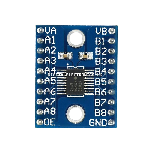
Pin Configuration and Descriptions
The logic converter typically has four channels and the following pin layout:
| Pin Name | Description |
|---|---|
| HV (High Voltage) | Connect to the high voltage supply (e.g., 5V). |
| LV (Low Voltage) | Connect to the low voltage supply (e.g., 3.3V). |
| GND | Ground connection (common ground for both voltage levels). |
| TXI1, TXI2, TXI3, TXI4 | Input pins for the low-voltage side (1.8V to 3.3V signals). |
| TXO1, TXO2, TXO3, TXO4 | Output pins for the high-voltage side (3.3V to 5V signals). |
| RXI1, RXI2, RXI3, RXI4 | Input pins for the high-voltage side (3.3V to 5V signals). |
| RXO1, RXO2, RXO3, RXO4 | Output pins for the low-voltage side (1.8V to 3.3V signals). |
Note: The exact pin configuration may vary depending on the specific logic converter module. Always refer to the datasheet of the module you are using.
Usage Instructions
How to Use the Component in a Circuit
Power Connections:
- Connect the HV pin to the high voltage supply (e.g., 5V).
- Connect the LV pin to the low voltage supply (e.g., 3.3V).
- Connect the GND pin to the common ground of the circuit.
Signal Connections:
- For signals going from low voltage to high voltage:
- Connect the low-voltage signal to the corresponding TXI pin.
- The converted high-voltage signal will be available at the corresponding TXO pin.
- For signals going from high voltage to low voltage:
- Connect the high-voltage signal to the corresponding RXI pin.
- The converted low-voltage signal will be available at the corresponding RXO pin.
- For signals going from low voltage to high voltage:
Protocol-Specific Notes:
- For I2C communication, connect the SDA and SCL lines to the appropriate channels on the logic converter.
- For SPI or UART, ensure the MOSI, MISO, SCK, TX, and RX lines are connected correctly.
Important Considerations and Best Practices
- Ensure the HV and LV voltage levels match the requirements of your devices.
- Use pull-up resistors on I2C lines if they are not already present in your circuit.
- Avoid exceeding the maximum voltage ratings to prevent damage to the logic converter.
- Keep the ground connections consistent across all devices in the circuit to avoid communication issues.
Example: Connecting to an Arduino UNO
Below is an example of using a logic converter to interface a 3.3V sensor with a 5V Arduino UNO:
Circuit Connections
- Connect the HV pin to the Arduino's 5V pin.
- Connect the LV pin to the sensor's 3.3V pin.
- Connect the GND pin to the common ground of the Arduino and sensor.
- Connect the sensor's data line to a TXI pin, and the corresponding TXO pin to the Arduino's input pin.
Arduino Code Example
// Example: Reading data from a 3.3V sensor using a logic level converter
// Ensure the sensor's data line is connected to TXI1, and TXO1 is connected to Arduino pin 2.

const int sensorPin = 2; // Arduino pin connected to the logic converter's TXO1

void setup() {
  Serial.begin(9600); // Initialize serial communication
  pinMode(sensorPin, INPUT); // Set the sensor pin as input
}

void loop() {
  int sensorValue = digitalRead(sensorPin); // Read the sensor value
  Serial.println(sensorValue); // Print the sensor value to the Serial Monitor
  delay(100); // Small delay for stability
}
Tip: Modify the code as needed based on the specific sensor or device you are using.
Troubleshooting and FAQs
Common Issues and Solutions
No Signal Conversion:
- Cause: Incorrect power connections.
- Solution: Verify that the HV and LV pins are connected to the correct voltage levels.
Communication Errors:
- Cause: Missing or incorrect pull-up resistors (for I2C).
- Solution: Add appropriate pull-up resistors to the SDA and SCL lines.
Signal Distortion:
- Cause: Excessive cable length or noise in the circuit.
- Solution: Use shorter cables and ensure proper grounding.
Overheating:
- Cause: Exceeding the voltage or current ratings.
- Solution: Check the datasheet and ensure the voltage levels are within the specified range.
FAQs
Q: Can I use a logic converter for analog signals?
A: No, logic converters are designed for digital signals only. Use a level shifter or voltage divider for analog signals.Q: Do I need separate power supplies for HV and LV?
A: Not necessarily. You can use a single power supply with voltage regulators to generate the required HV and LV levels.Q: Can I use a logic converter for bidirectional communication?
A: Yes, most logic converters support bidirectional communication, especially for protocols like I2C.
By following this documentation, you can effectively use a logic converter in your projects to bridge voltage gaps and ensure reliable communication between devices.