Cirkit Designer Logo
Cirkit Designer
Your all-in-one circuit design IDE
Home / 
Component Documentation

How to Use XL6015 BUST CONVERTOR : Examples, Pinouts, and Specs

Image of XL6015 BUST CONVERTOR
Cirkit Designer LogoDesign with XL6015 BUST CONVERTOR in Cirkit Designer

Introduction

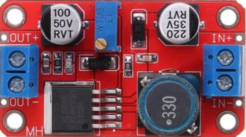
The XL6015 is a high-efficiency, step-up (boost) DC-DC converter module capable of driving a 0.8A load with excellent line and load regulation. This module is widely used for converting lower input voltages to higher output voltages, making it ideal for applications where a stable power supply at a higher voltage level is required. Common applications include battery-powered devices, portable electronics, and power supply for electronic equipment.

Explore Projects Built with XL6015 BUST CONVERTOR

Use Cirkit Designer to design, explore, and prototype these projects online. Some projects support real-time simulation. Click "Open Project" to start designing instantly!
Battery-Powered Boost Converter with USB Type-C and BMS
Image of Weird Case: A project utilizing XL6015 BUST CONVERTOR  in a practical application
This circuit is a power management and conversion system that includes a boost converter, battery management system (BMS), and various MOSFETs and passive components. It is designed to regulate and boost the voltage from a 2000mAh battery, providing stable power output through a USB Type C interface. The circuit also includes protection and switching mechanisms to ensure safe and efficient power delivery.
Cirkit Designer LogoOpen Project in Cirkit Designer
Battery-Powered DC-DC Converter System for Multi-Voltage Power Distribution
Image of test 1 ih: A project utilizing XL6015 BUST CONVERTOR  in a practical application
This circuit converts a 38.5V battery output to multiple lower voltage levels using a series of DC-DC converters and a power module. It includes an emergency stop switch for safety and distributes power to various components such as a relay module, USB ports, and a bus servo adaptor.
Cirkit Designer LogoOpen Project in Cirkit Designer
Battery-Powered DC Generator with XL4015 Buck Converter
Image of conveyor: A project utilizing XL6015 BUST CONVERTOR  in a practical application
This circuit consists of a 12V battery connected to a rocker switch, which controls the input to an XL4015 DC Buck Step-down converter. The converter steps down the voltage to power a DC generator, with the generator's output connected back to the converter to form a feedback loop.
Cirkit Designer LogoOpen Project in Cirkit Designer
Dual Motor Control Circuit with Directional Switching and Voltage Regulation
Image of Pencuci Kipas: A project utilizing XL6015 BUST CONVERTOR  in a practical application
This circuit features a 12V battery connected through a rocker switch to two buck converters, one of which steps down the voltage to power two DC mini metal gear motors, and the other is connected to a directional switch that controls a third DC mini metal gear motor. The XL4015 5A DC Buck Step-down converter's output is connected to two motors, allowing them to run at a reduced voltage, while the other buck converter's output is routed through a directional switch to control the direction of the third motor.
Cirkit Designer LogoOpen Project in Cirkit Designer

Explore Projects Built with XL6015 BUST CONVERTOR

Use Cirkit Designer to design, explore, and prototype these projects online. Some projects support real-time simulation. Click "Open Project" to start designing instantly!
Image of Weird Case: A project utilizing XL6015 BUST CONVERTOR  in a practical application
Battery-Powered Boost Converter with USB Type-C and BMS
This circuit is a power management and conversion system that includes a boost converter, battery management system (BMS), and various MOSFETs and passive components. It is designed to regulate and boost the voltage from a 2000mAh battery, providing stable power output through a USB Type C interface. The circuit also includes protection and switching mechanisms to ensure safe and efficient power delivery.
Cirkit Designer LogoOpen Project in Cirkit Designer
Image of test 1 ih: A project utilizing XL6015 BUST CONVERTOR  in a practical application
Battery-Powered DC-DC Converter System for Multi-Voltage Power Distribution
This circuit converts a 38.5V battery output to multiple lower voltage levels using a series of DC-DC converters and a power module. It includes an emergency stop switch for safety and distributes power to various components such as a relay module, USB ports, and a bus servo adaptor.
Cirkit Designer LogoOpen Project in Cirkit Designer
Image of conveyor: A project utilizing XL6015 BUST CONVERTOR  in a practical application
Battery-Powered DC Generator with XL4015 Buck Converter
This circuit consists of a 12V battery connected to a rocker switch, which controls the input to an XL4015 DC Buck Step-down converter. The converter steps down the voltage to power a DC generator, with the generator's output connected back to the converter to form a feedback loop.
Cirkit Designer LogoOpen Project in Cirkit Designer
Image of Pencuci Kipas: A project utilizing XL6015 BUST CONVERTOR  in a practical application
Dual Motor Control Circuit with Directional Switching and Voltage Regulation
This circuit features a 12V battery connected through a rocker switch to two buck converters, one of which steps down the voltage to power two DC mini metal gear motors, and the other is connected to a directional switch that controls a third DC mini metal gear motor. The XL4015 5A DC Buck Step-down converter's output is connected to two motors, allowing them to run at a reduced voltage, while the other buck converter's output is routed through a directional switch to control the direction of the third motor.
Cirkit Designer LogoOpen Project in Cirkit Designer

Technical Specifications

Key Technical Details

  • Input Voltage Range: 5V to 32V DC
  • Output Voltage Range: 5V to 35V DC (adjustable via onboard potentiometer)
  • Output Current: Up to 0.8A (with proper heat sinking)
  • Switching Frequency: 400kHz
  • Efficiency: Up to 94% (depends on input/output voltage, current, and voltage differential)

Pin Configuration and Descriptions

Pin Number Name Description
1 VIN Input voltage (5V to 32V DC)
2 GND Ground connection
3 VOUT Output voltage (5V to 35V DC)
4 EN Enable pin (pull to ground to disable module)

Usage Instructions

How to Use the Component in a Circuit

  1. Connecting Power: Connect the input voltage (5V to 32V DC) to the VIN and GND pins. Ensure that the input voltage does not exceed the specified maximum to avoid damage.
  2. Adjusting Output Voltage: Turn the onboard potentiometer to adjust the output voltage. Use a multimeter to monitor the VOUT pin until the desired voltage is reached.
  3. Load Connection: Connect the load to the VOUT and GND pins. Ensure that the load does not draw more than 0.8A to maintain module performance.
  4. Enabling/Disabling the Module: The EN pin can be used to enable or disable the module. Pulling this pin to ground will disable the module, conserving power when not in use.

Important Considerations and Best Practices

  • Heat Dissipation: If the module is expected to deliver high output currents or if there is a significant voltage difference between input and output, proper heat sinking or airflow should be provided to prevent overheating.
  • Input Capacitor: It is recommended to use a good quality electrolytic capacitor at the input to minimize voltage spikes and provide a stable voltage source.
  • Output Capacitor: Similarly, an electrolytic capacitor at the output can help maintain a stable output voltage during transient load changes.
  • Inductive Loads: If driving inductive loads, a diode may be necessary across the load to protect the module from voltage spikes.

Troubleshooting and FAQs

Common Issues

  • Output Voltage Not Adjusting: Ensure the potentiometer is functioning correctly and that the connections to the VOUT pin are secure.
  • Module Overheating: Check the current draw of the load and ensure it is within the module's limits. Improve heat dissipation if necessary.
  • No Output Voltage: Verify that the input voltage is within the specified range and that the EN pin is not pulled to ground.

Solutions and Tips for Troubleshooting

  • Check Connections: Loose connections can often cause issues. Ensure all connections are secure and well-soldered.
  • Measure Input Voltage: Use a multimeter to confirm that the input voltage is within the specified range and is stable.
  • Inspect for Damage: Look for any visible signs of damage to the module, such as burnt components or traces, which could indicate a failure.

FAQs

Q: Can I use the XL6015 to charge batteries? A: Yes, but you must ensure that the output voltage is set correctly for the battery type and that the charging current does not exceed the module's limit.

Q: What is the maximum input voltage for the XL6015? A: The maximum input voltage is 32V DC. Exceeding this voltage can damage the module.

Q: How can I enable or disable the module using an Arduino? A: You can connect the EN pin to an Arduino digital pin and set it HIGH to disable the module or LOW to enable it. Remember to configure the pin as an output in your Arduino sketch.

// Example code to enable/disable XL6015 using an Arduino UNO
const int enablePin = 7; // Connect the EN pin of XL6015 to digital pin 7

void setup() {
  pinMode(enablePin, OUTPUT);
  // To enable the XL6015, set the enablePin LOW
  digitalWrite(enablePin, LOW);
}

void loop() {
  // Your code here
  // To disable the XL6015, set the enablePin HIGH
  // digitalWrite(enablePin, HIGH);
}

Q: Is it possible to get a higher output current than 0.8A? A: The XL6015 is rated for 0.8A without additional cooling. To exceed this, you would need to provide significant heat dissipation, but it is not recommended as it may reduce the lifespan of the module or cause it to fail.

This documentation provides a comprehensive guide to using the XL6015 boost converter module. For further assistance or technical support, please consult the manufacturer's datasheet or contact technical support.