
How to Use EBYTE E01-ML01DP5 : Examples, Pinouts, and Specs
 Design with EBYTE E01-ML01DP5 in Cirkit Designer
Introduction
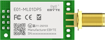
The EBYTE E01-ML01DP5 is a high-performance, low-power wireless transceiver module operating on the 433MHz frequency band. It is based on the nRF24L01+ chip and features a built-in power amplifier and low-noise amplifier, enabling long-range communication of up to 3 kilometers in open environments. This module is ideal for applications requiring reliable, long-distance data transmission, such as IoT projects, remote control systems, telemetry, and industrial automation.
Explore Projects Built with EBYTE E01-ML01DP5
 Open Project in Cirkit Designer
 Open Project in Cirkit Designer
 Open Project in Cirkit Designer
 Open Project in Cirkit Designer
Explore Projects Built with EBYTE E01-ML01DP5
Open Project in Cirkit DesignerOpen Project in Cirkit DesignerOpen Project in Cirkit DesignerOpen Project in Cirkit DesignerCommon Applications:
- Internet of Things (IoT): Smart agriculture, environmental monitoring, and smart cities.
- Remote Control Systems: Drones, RC vehicles, and home automation.
- Telemetry: Data collection and monitoring in industrial or scientific applications.
- Wireless Sensor Networks: Long-range communication between sensors and gateways.
Technical Specifications
Key Technical Details:
| Parameter | Value |
|---|---|
| Frequency Band | 433 MHz |
| Modulation | GFSK (Gaussian Frequency Shift Keying) |
| Maximum Data Rate | 2 Mbps |
| Transmission Power | Up to 20 dBm (100 mW) |
| Receiver Sensitivity | -95 dBm |
| Communication Range | Up to 3 km (line of sight) |
| Operating Voltage | 1.9V to 3.6V |
| Current Consumption | 115 mA (TX mode), 13.5 mA (RX mode) |
| Operating Temperature | -40°C to +85°C |
| Dimensions | 24 mm x 43 mm |
| Interface | SPI |
Pin Configuration and Descriptions:
The E01-ML01DP5 module has 8 pins. Below is the pinout and description:
| Pin Number | Pin Name | Description |
|---|---|---|
| 1 | GND | Ground (0V reference) |
| 2 | VCC | Power supply (1.9V to 3.6V) |
| 3 | CE | Chip Enable: Activates RX/TX mode |
| 4 | CSN | Chip Select: SPI enable (active low) |
| 5 | SCK | SPI Clock |
| 6 | MOSI | SPI Master Out Slave In |
| 7 | MISO | SPI Master In Slave Out |
| 8 | IRQ | Interrupt Request: Indicates data received |
Usage Instructions
How to Use the E01-ML01DP5 in a Circuit:
Power Supply:
- Connect the VCC pin to a regulated power source between 1.9V and 3.6V.
- Connect the GND pin to the ground of your circuit.
SPI Communication:
- Connect the CSN, SCK, MOSI, and MISO pins to the corresponding SPI pins on your microcontroller.
- Use the CE pin to toggle between RX (receive) and TX (transmit) modes.
Antenna Connection:
- Attach a 433MHz antenna to the module's SMA connector for optimal range and performance.
Interrupt Handling:
- Use the IRQ pin to detect events such as data reception or transmission completion.
Software Configuration:
- Configure the module using SPI commands. Set parameters such as frequency, data rate, and power level.
Important Considerations:
- Power Supply Stability: Ensure a stable power supply with minimal noise to avoid communication errors.
- Antenna Placement: Position the antenna away from metal objects or other sources of interference.
- SPI Speed: Use an SPI clock speed of up to 10 MHz for reliable communication.
- Regulatory Compliance: Ensure compliance with local regulations for 433MHz frequency usage.
Example: Connecting to an Arduino UNO
Below is an example of how to connect and program the E01-ML01DP5 with an Arduino UNO:
Wiring Diagram:
| E01-ML01DP5 Pin | Arduino UNO Pin |
|---|---|
| VCC | 3.3V |
| GND | GND |
| CE | Pin 9 |
| CSN | Pin 10 |
| SCK | Pin 13 |
| MOSI | Pin 11 |
| MISO | Pin 12 |
| IRQ | Pin 2 |
Arduino Code Example:
#include <SPI.h>
#include <nRF24L01.h>
#include <RF24.h>

// Define the CE and CSN pins
#define CE_PIN 9
#define CSN_PIN 10

// Create an RF24 object
RF24 radio(CE_PIN, CSN_PIN);

// Define the address for communication
const byte address[6] = "00001";

void setup() {
  // Initialize serial communication for debugging
  Serial.begin(9600);

  // Initialize the RF24 module
  radio.begin();

  // Set the communication address
  radio.openWritingPipe(address);

  // Set RF24 module to transmit mode
  radio.setPALevel(RF24_PA_HIGH);

  // Start the radio in standby mode
  radio.stopListening();
}

void loop() {
  // Data to send
  const char text[] = "Hello, EBYTE!";

  // Send the data
  bool success = radio.write(&text, sizeof(text));

  // Print the result to the serial monitor
  if (success) {
    Serial.println("Data sent successfully!");
  } else {
    Serial.println("Data transmission failed.");
  }

  // Wait before sending the next message
  delay(1000);
}
Troubleshooting and FAQs
Common Issues:
No Communication Between Modules:
- Ensure both modules are configured with the same frequency, data rate, and address.
- Verify the SPI connections and ensure the microcontroller is properly communicating with the module.
Short Communication Range:
- Check the antenna connection and ensure it is securely attached.
- Avoid obstructions or interference from other devices operating on the 433MHz band.
High Current Consumption:
- Verify that the module is not stuck in TX mode. Use the CE pin to toggle modes appropriately.
Module Not Responding:
- Ensure the power supply voltage is within the specified range (1.9V to 3.6V).
- Check the SPI clock speed and reduce it if necessary.
FAQs:
Q: Can I use the E01-ML01DP5 with a 5V microcontroller?
A: Yes, but you must use a level shifter or voltage divider for the SPI pins, as the module operates at 3.3V logic levels.
Q: What is the maximum data rate supported by the module?
A: The module supports data rates of 250 kbps, 1 Mbps, and 2 Mbps.
Q: How can I increase the communication range?
A: Use a high-gain antenna, ensure line-of-sight communication, and reduce the data rate to improve sensitivity.
Q: Is the module compatible with other nRF24L01+ modules?
A: Yes, the E01-ML01DP5 is fully compatible with other nRF24L01+ modules.
This concludes the documentation for the EBYTE E01-ML01DP5. For further assistance, refer to the manufacturer's datasheet or contact EBYTE support.