Cirkit Designer Logo
Cirkit Designer
Your all-in-one circuit design IDE
Home / 
Component Documentation

How to Use Water Level Detection Module: Examples, Pinouts, and Specs

Image of Water Level Detection Module
Cirkit Designer LogoDesign with Water Level Detection Module in Cirkit Designer

Introduction

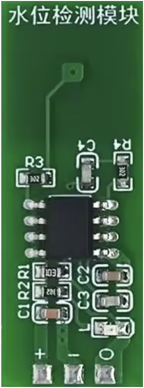
The Water Level Detection Module (ESP32 M04) is a versatile electronic component designed to measure the level of water in tanks, reservoirs, or other liquid storage systems. It uses sensors to detect the presence or absence of water at various levels and provides output signals for monitoring or control purposes. This module is ideal for applications requiring water level monitoring, such as automated water pumps, irrigation systems, and water tank overflow prevention.

Explore Projects Built with Water Level Detection Module

Use Cirkit Designer to design, explore, and prototype these projects online. Some projects support real-time simulation. Click "Open Project" to start designing instantly!
ESP8266 NodeMCU Controlled Smart Dam Monitoring System with I2C LCD Display and SIM900A GSM Module
Image of fyp: A project utilizing Water Level Detection Module in a practical application
This circuit is designed for smart dam monitoring, featuring an ESP8266 NodeMCU microcontroller that interfaces with an I2C LCD screen for display, a SIM900A module for cellular communication, and an HC-SR04 ultrasonic sensor for water level detection. The NodeMCU collects water level data from the ultrasonic sensor and displays alerts on the LCD screen, while also communicating this information via the SIM900A module, potentially for remote monitoring or control purposes.
Cirkit Designer LogoOpen Project in Cirkit Designer
Arduino-Controlled Ultrasonic Water Level Monitoring and Pump Management System
Image of auto water: A project utilizing Water Level Detection Module in a practical application
This circuit is designed to monitor water levels using an HC-SR04 Ultrasonic Sensor and display the information on a 20x4 LCD with I2C interface, controlled by an Arduino UNO. When the water level falls below a predefined threshold, the Arduino activates a relay module, which in turn powers a mini diaphragm water pump to refill the tank. The system aims to maintain water levels within set boundaries, automating the process of water level management.
Cirkit Designer LogoOpen Project in Cirkit Designer
Arduino UNO Flood Management System with Ultrasonic Sensor and Wi-Fi Connectivity
Image of Flood1: A project utilizing Water Level Detection Module in a practical application
This circuit is a flood management system that uses an Arduino UNO to monitor water levels, temperature, and humidity. It employs an HC-SR04 ultrasonic sensor for distance measurement, a DHT11 sensor for temperature and humidity, and displays the data on a 16x2 I2C LCD. Additionally, it includes a piezo buzzer and LEDs to provide alerts when water levels exceed a safety threshold.
Cirkit Designer LogoOpen Project in Cirkit Designer
NodeMCU ESP8266 Flood Monitoring System with GSM Alert and Ultrasonic Sensor
Image of asd: A project utilizing Water Level Detection Module in a practical application
This circuit is designed for a flood monitoring system. It uses a NodeMCU ESP8266 to read data from an HC-SR04 ultrasonic sensor and a float switch to detect water levels, and displays this information on an I2C LCD screen. Additionally, the circuit can send SMS alerts via a SIM800L GSM module when the water level exceeds a predefined threshold, indicating potential flooding.
Cirkit Designer LogoOpen Project in Cirkit Designer

Explore Projects Built with Water Level Detection Module

Use Cirkit Designer to design, explore, and prototype these projects online. Some projects support real-time simulation. Click "Open Project" to start designing instantly!
Image of fyp: A project utilizing Water Level Detection Module in a practical application
ESP8266 NodeMCU Controlled Smart Dam Monitoring System with I2C LCD Display and SIM900A GSM Module
This circuit is designed for smart dam monitoring, featuring an ESP8266 NodeMCU microcontroller that interfaces with an I2C LCD screen for display, a SIM900A module for cellular communication, and an HC-SR04 ultrasonic sensor for water level detection. The NodeMCU collects water level data from the ultrasonic sensor and displays alerts on the LCD screen, while also communicating this information via the SIM900A module, potentially for remote monitoring or control purposes.
Cirkit Designer LogoOpen Project in Cirkit Designer
Image of auto water: A project utilizing Water Level Detection Module in a practical application
Arduino-Controlled Ultrasonic Water Level Monitoring and Pump Management System
This circuit is designed to monitor water levels using an HC-SR04 Ultrasonic Sensor and display the information on a 20x4 LCD with I2C interface, controlled by an Arduino UNO. When the water level falls below a predefined threshold, the Arduino activates a relay module, which in turn powers a mini diaphragm water pump to refill the tank. The system aims to maintain water levels within set boundaries, automating the process of water level management.
Cirkit Designer LogoOpen Project in Cirkit Designer
Image of Flood1: A project utilizing Water Level Detection Module in a practical application
Arduino UNO Flood Management System with Ultrasonic Sensor and Wi-Fi Connectivity
This circuit is a flood management system that uses an Arduino UNO to monitor water levels, temperature, and humidity. It employs an HC-SR04 ultrasonic sensor for distance measurement, a DHT11 sensor for temperature and humidity, and displays the data on a 16x2 I2C LCD. Additionally, it includes a piezo buzzer and LEDs to provide alerts when water levels exceed a safety threshold.
Cirkit Designer LogoOpen Project in Cirkit Designer
Image of asd: A project utilizing Water Level Detection Module in a practical application
NodeMCU ESP8266 Flood Monitoring System with GSM Alert and Ultrasonic Sensor
This circuit is designed for a flood monitoring system. It uses a NodeMCU ESP8266 to read data from an HC-SR04 ultrasonic sensor and a float switch to detect water levels, and displays this information on an I2C LCD screen. Additionally, the circuit can send SMS alerts via a SIM800L GSM module when the water level exceeds a predefined threshold, indicating potential flooding.
Cirkit Designer LogoOpen Project in Cirkit Designer

Common Applications and Use Cases

  • Water Tank Monitoring: Automatically detect and maintain water levels in storage tanks.
  • Irrigation Systems: Control water flow based on soil or tank water levels.
  • Flood Detection: Monitor water levels in flood-prone areas.
  • Industrial Automation: Manage liquid levels in industrial processes.
  • Home Automation: Integrate with smart home systems for water management.

Technical Specifications

The following table outlines the key technical details of the ESP32 M04 Water Level Detection Module:

Parameter Specification
Manufacturer ESP32
Part ID M04
Operating Voltage 3.3V to 5V DC
Operating Current ≤ 20mA
Output Type Digital (High/Low) and Analog Signal
Detection Range 0 to 100% water level
Sensor Type Capacitive or Resistive (varies)
Dimensions 50mm x 20mm x 10mm
Operating Temperature -10°C to 60°C
Interface 3-pin (VCC, GND, Signal)

Pin Configuration and Descriptions

The module has a 3-pin interface for easy integration into circuits. The pin configuration is as follows:

Pin Name Description
1 VCC Power supply input (3.3V to 5V DC). Connect to the positive terminal of the power source.
2 GND Ground connection. Connect to the negative terminal of the power source.
3 Signal Output signal pin. Provides a digital HIGH/LOW or analog voltage based on water level.

Usage Instructions

How to Use the Component in a Circuit

  1. Power the Module: Connect the VCC pin to a 3.3V or 5V DC power source and the GND pin to the ground.
  2. Connect the Signal Pin:
    • For digital output, connect the Signal pin to a digital input pin on a microcontroller (e.g., ESP32 or Arduino UNO).
    • For analog output, connect the Signal pin to an analog input pin on the microcontroller.
  3. Place the Sensor: Submerge the sensor in the water tank or reservoir at the desired level for detection.
  4. Read the Output:
    • A HIGH signal indicates water presence, while a LOW signal indicates absence (for digital mode).
    • For analog mode, the voltage varies proportionally with the water level.

Important Considerations and Best Practices

  • Power Supply: Ensure the module is powered within the specified voltage range (3.3V to 5V DC).
  • Sensor Placement: Position the sensor securely to avoid false readings due to movement or turbulence.
  • Water Type: The module may behave differently in pure, distilled, or highly conductive water. Test in your specific application.
  • Signal Noise: Use proper grounding and shielding to minimize noise in the output signal.
  • Arduino Compatibility: The module is compatible with Arduino UNO and other microcontrollers. Below is an example code snippet for interfacing with an Arduino UNO.

Example Code for Arduino UNO

// Water Level Detection Module Example Code
// This code reads the digital and analog output of the module and displays
// the water level status on the serial monitor.

const int signalPin = A0; // Signal pin connected to analog pin A0
const int digitalPin = 2; // Signal pin connected to digital pin 2

void setup() {
  pinMode(digitalPin, INPUT); // Set digital pin as input
  Serial.begin(9600);        // Initialize serial communication
}

void loop() {
  int analogValue = analogRead(signalPin); // Read analog signal
  int digitalValue = digitalRead(digitalPin); // Read digital signal

  // Display analog water level value
  Serial.print("Analog Water Level: ");
  Serial.println(analogValue);

  // Display digital water presence status
  if (digitalValue == HIGH) {
    Serial.println("Water Detected (Digital Output: HIGH)");
  } else {
    Serial.println("No Water Detected (Digital Output: LOW)");
  }

  delay(1000); // Wait for 1 second before the next reading
}

Troubleshooting and FAQs

Common Issues Users Might Face

  1. No Output Signal:

    • Cause: Incorrect wiring or insufficient power supply.
    • Solution: Double-check the connections and ensure the power supply is within the specified range.
  2. Inconsistent Readings:

    • Cause: Sensor movement or water turbulence.
    • Solution: Secure the sensor in a stable position and avoid placing it near water inlets.
  3. Analog Output Not Varying:

    • Cause: Faulty sensor or improper connection to the analog pin.
    • Solution: Test the sensor with a multimeter and verify the analog pin connection.
  4. Digital Output Always HIGH or LOW:

    • Cause: Sensor not submerged or damaged.
    • Solution: Ensure the sensor is properly submerged and test with a known water level.

Solutions and Tips for Troubleshooting

  • Test the Module Independently: Before integrating into a larger system, test the module with a simple circuit to verify functionality.
  • Check for Corrosion: If the module is used in harsh environments, inspect for corrosion or damage to the sensor.
  • Use Pull-Up Resistors: For digital output, use pull-up resistors if the signal is unstable.
  • Monitor Power Supply: Ensure a stable and noise-free power supply to avoid erratic behavior.

By following this documentation, users can effectively integrate and troubleshoot the ESP32 M04 Water Level Detection Module in their projects.