Cirkit Designer Logo
Cirkit Designer
Your all-in-one circuit design IDE
Home / 
Component Documentation

How to Use 10KOHM Potentiometer: Examples, Pinouts, and Specs

Image of 10KOHM Potentiometer
Cirkit Designer LogoDesign with 10KOHM Potentiometer in Cirkit Designer

Introduction

The 10KΩ potentiometer is a variable resistor that allows users to adjust voltage levels in a circuit, thereby controlling the flow of current. It is a versatile component commonly used in applications such as volume control in audio devices, brightness adjustment in displays, and as an input device in various electronic projects. Its ability to provide fine-tuned resistance makes it an essential component in both analog and digital circuits.

Explore Projects Built with 10KOHM Potentiometer

Use Cirkit Designer to design, explore, and prototype these projects online. Some projects support real-time simulation. Click "Open Project" to start designing instantly!
Teensy 4.1-Based Multi-Channel Potentiometer Interface with 74HC4051 Mux and AMS1117 3.3V Regulator
Image of redrum: A project utilizing 10KOHM Potentiometer in a practical application
This circuit features a Teensy 4.1 microcontroller interfaced with a SparkFun 74HC4051 8-channel multiplexer to read multiple rotary potentiometers. The AMS1117 3.3V voltage regulator provides a stable 3.3V supply to the multiplexer and potentiometers, while electrolytic and ceramic capacitors are used for power supply filtering and stabilization.
Cirkit Designer LogoOpen Project in Cirkit Designer
Arduino UNO Based Oscilloscope with OLED Display and Adjustable Time/Voltage Scales
Image of 1: A project utilizing 10KOHM Potentiometer in a practical application
This circuit features an Arduino UNO connected to a 0.96" OLED display for visual output, with a rotary potentiometer providing analog input to the Arduino. Two pushbuttons are included, each with a pull-up resistor, to allow the user to adjust time base and voltage scale settings for the display. The Arduino runs a sketch to read the potentiometer value, adjust settings with the pushbuttons, and display a scaled waveform on the OLED screen.
Cirkit Designer LogoOpen Project in Cirkit Designer
Teensy 4.1-Based Multi-Channel Analog Input System with Potentiometer Control
Image of going with 16 channel mux: A project utilizing 10KOHM Potentiometer in a practical application
This circuit is a multi-channel analog input system that uses a Teensy 4.1 microcontroller to read multiple potentiometers through an 8-channel and a 16-channel multiplexer. The circuit includes voltage regulation using an AMS1117 3.3V regulator and capacitors for power stabilization.
Cirkit Designer LogoOpen Project in Cirkit Designer
Arduino UNO Potentiometer-Controlled LED with Resistor
Image of Senior: A project utilizing 10KOHM Potentiometer in a practical application
This circuit uses an Arduino UNO to read the analog output of a potentiometer connected to its A0 pin, with the potentiometer powered by the 5V and GND pins of the Arduino. Additionally, a 200-ohm resistor is connected to the D13 digital pin of the Arduino, likely for an LED or other output device.
Cirkit Designer LogoOpen Project in Cirkit Designer

Explore Projects Built with 10KOHM Potentiometer

Use Cirkit Designer to design, explore, and prototype these projects online. Some projects support real-time simulation. Click "Open Project" to start designing instantly!
Image of redrum: A project utilizing 10KOHM Potentiometer in a practical application
Teensy 4.1-Based Multi-Channel Potentiometer Interface with 74HC4051 Mux and AMS1117 3.3V Regulator
This circuit features a Teensy 4.1 microcontroller interfaced with a SparkFun 74HC4051 8-channel multiplexer to read multiple rotary potentiometers. The AMS1117 3.3V voltage regulator provides a stable 3.3V supply to the multiplexer and potentiometers, while electrolytic and ceramic capacitors are used for power supply filtering and stabilization.
Cirkit Designer LogoOpen Project in Cirkit Designer
Image of 1: A project utilizing 10KOHM Potentiometer in a practical application
Arduino UNO Based Oscilloscope with OLED Display and Adjustable Time/Voltage Scales
This circuit features an Arduino UNO connected to a 0.96" OLED display for visual output, with a rotary potentiometer providing analog input to the Arduino. Two pushbuttons are included, each with a pull-up resistor, to allow the user to adjust time base and voltage scale settings for the display. The Arduino runs a sketch to read the potentiometer value, adjust settings with the pushbuttons, and display a scaled waveform on the OLED screen.
Cirkit Designer LogoOpen Project in Cirkit Designer
Image of going with 16 channel mux: A project utilizing 10KOHM Potentiometer in a practical application
Teensy 4.1-Based Multi-Channel Analog Input System with Potentiometer Control
This circuit is a multi-channel analog input system that uses a Teensy 4.1 microcontroller to read multiple potentiometers through an 8-channel and a 16-channel multiplexer. The circuit includes voltage regulation using an AMS1117 3.3V regulator and capacitors for power stabilization.
Cirkit Designer LogoOpen Project in Cirkit Designer
Image of Senior: A project utilizing 10KOHM Potentiometer in a practical application
Arduino UNO Potentiometer-Controlled LED with Resistor
This circuit uses an Arduino UNO to read the analog output of a potentiometer connected to its A0 pin, with the potentiometer powered by the 5V and GND pins of the Arduino. Additionally, a 200-ohm resistor is connected to the D13 digital pin of the Arduino, likely for an LED or other output device.
Cirkit Designer LogoOpen Project in Cirkit Designer

Technical Specifications

  • Resistance Value: 10KΩ (10,000 ohms)
  • Type: Rotary potentiometer
  • Adjustment: Manual (via a rotating knob or shaft)
  • Power Rating: Typically 0.25W (check specific model for exact rating)
  • Tolerance: ±10% (varies by manufacturer)
  • Operating Voltage: Up to 50V (varies by model)
  • Temperature Range: -10°C to +70°C (varies by model)
  • Lifespan: Typically 10,000 to 50,000 cycles

Pin Configuration and Descriptions

The 10KΩ potentiometer typically has three pins:

Pin Name Description
1 Terminal 1 (T1) One end of the resistive track. Connects to the input voltage or ground.
2 Wiper (W) The adjustable middle pin. Outputs a variable voltage based on the knob position.
3 Terminal 2 (T2) The other end of the resistive track. Connects to ground or input voltage.

Usage Instructions

How to Use the 10KΩ Potentiometer in a Circuit

  1. Basic Connection:

    • Connect Terminal 1 (T1) to the input voltage (e.g., 5V).
    • Connect Terminal 2 (T2) to ground (GND).
    • Connect the Wiper (W) to the input of the circuit where you need a variable voltage.
  2. Adjusting Resistance:

    • Rotate the potentiometer's knob or shaft to change the resistance between the wiper and the terminals.
    • The voltage at the wiper will vary proportionally to the position of the knob.
  3. Example Application:

    • Use the potentiometer to control the brightness of an LED by connecting the wiper to the LED's input and adjusting the knob to vary the voltage.

Important Considerations and Best Practices

  • Power Rating: Ensure the power dissipation across the potentiometer does not exceed its rated power (e.g., 0.25W).
  • Mechanical Stress: Avoid applying excessive force to the knob or shaft to prevent damage.
  • Debouncing: In digital applications, consider software debouncing if the potentiometer is used as an input device.
  • Noise: In sensitive circuits, the wiper may introduce noise. Use a capacitor across the wiper and ground to filter it.

Arduino UNO Example Code

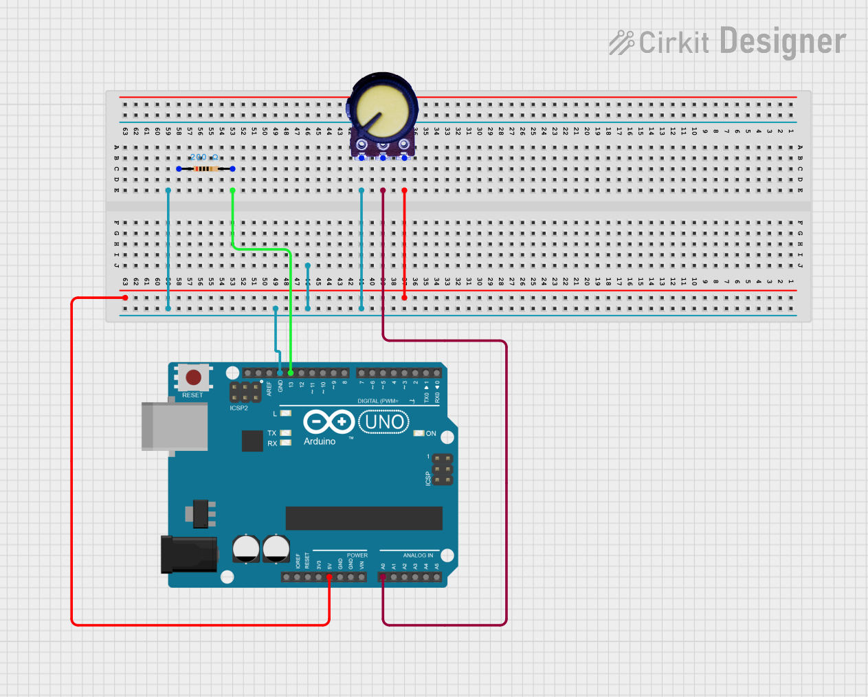
The 10KΩ potentiometer can be used with an Arduino UNO to read analog input values. Below is an example:

// Example: Reading a 10KΩ potentiometer with Arduino UNO
// Connect the potentiometer's T1 to 5V, T2 to GND, and Wiper to A0.

const int potPin = A0; // Analog pin connected to the potentiometer's wiper
int potValue = 0;      // Variable to store the potentiometer value

void setup() {
  Serial.begin(9600); // Initialize serial communication at 9600 baud
}

void loop() {
  potValue = analogRead(potPin); // Read the analog value (0-1023)
  Serial.print("Potentiometer Value: ");
  Serial.println(potValue); // Print the value to the Serial Monitor
  delay(100); // Small delay for stability
}

Troubleshooting and FAQs

Common Issues

  1. No Output Voltage:

    • Cause: Incorrect wiring.
    • Solution: Verify that Terminal 1 is connected to the input voltage, Terminal 2 to ground, and the wiper to the circuit input.
  2. Inconsistent or Noisy Output:

    • Cause: Dust or wear on the resistive track.
    • Solution: Clean the potentiometer with contact cleaner or replace it if worn out.
  3. Potentiometer Not Adjusting Properly:

    • Cause: Mechanical damage or incorrect connections.
    • Solution: Inspect for physical damage and ensure proper wiring.

FAQs

  • Q: Can I use the 10KΩ potentiometer to control high-power devices?
    A: No, the potentiometer is not designed for high-power applications. Use it to control low-power signals or as part of a larger circuit with a transistor or MOSFET for high-power control.

  • Q: How do I know the resistance value of my potentiometer?
    A: The resistance value (e.g., 10KΩ) is usually printed on the body of the potentiometer.

  • Q: Can I use the potentiometer as a fixed resistor?
    A: Yes, by setting the wiper to a specific position and not adjusting it, the potentiometer can act as a fixed resistor.

By following this documentation, you can effectively use the 10KΩ potentiometer in your electronic projects.