How to Use Vfd: Examples, Pinouts, and Specs
Introduction
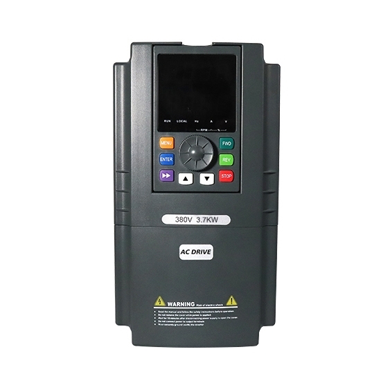
A Variable Frequency Drive (VFD) is an electronic device designed to control the speed and torque of an electric motor by adjusting the frequency and voltage of the power supplied to the motor. This capability makes VFDs an essential component in modern industrial and commercial applications where precise motor control is required.
Explore Projects Built with Vfd


Explore Projects Built with Vfd
Common Applications and Use Cases
- Industrial Automation: Used in conveyor belts, pumps, and fans to optimize energy consumption.
- HVAC Systems: Controls the speed of fans and compressors for efficient heating, ventilation, and air conditioning.
- Energy Savings: Reduces power consumption by matching motor speed to load requirements.
- Process Control: Provides precise control over motor speed for applications like mixers, grinders, and extruders.
- Soft Starting: Gradually ramps up motor speed to reduce mechanical stress and electrical surges.
Technical Specifications
Below are the general technical specifications for a typical VFD. Note that specific models may vary.
Key Technical Details
- Input Voltage: 110V AC, 220V AC, or 480V AC (single-phase or three-phase)
- Output Voltage: Adjustable, typically matches the input voltage
- Frequency Range: 0 Hz to 400 Hz
- Power Rating: 0.5 kW to 500 kW (varies by model)
- Control Modes: V/f (Voltage/Frequency), Vector Control, Direct Torque Control (DTC)
- Efficiency: Typically >95%
- Operating Temperature: -10°C to 50°C
- Communication Protocols: Modbus, CAN, Ethernet (varies by model)
Pin Configuration and Descriptions
The following table outlines the typical terminal connections for a VFD:
| Pin/Terminal | Label | Description |
|---|---|---|
| 1 | L1 | Input power phase 1 (for single-phase or three-phase input) |
| 2 | L2 | Input power phase 2 (for three-phase input) |
| 3 | L3 | Input power phase 3 (for three-phase input) |
| 4 | U | Output to motor phase U |
| 5 | V | Output to motor phase V |
| 6 | W | Output to motor phase W |
| 7 | GND | Ground connection for safety |
| 8 | COM | Communication ground for control signals |
| 9 | AI | Analog input for speed control (e.g., 0-10V or 4-20mA) |
| 10 | DI1 | Digital input 1 (e.g., start/stop control) |
| 11 | DI2 | Digital input 2 (e.g., forward/reverse control) |
| 12 | DO | Digital output (e.g., fault or status signal) |
| 13 | RS485+ | RS485 communication positive terminal (for Modbus or other protocols) |
| 14 | RS485- | RS485 communication negative terminal (for Modbus or other protocols) |
Usage Instructions
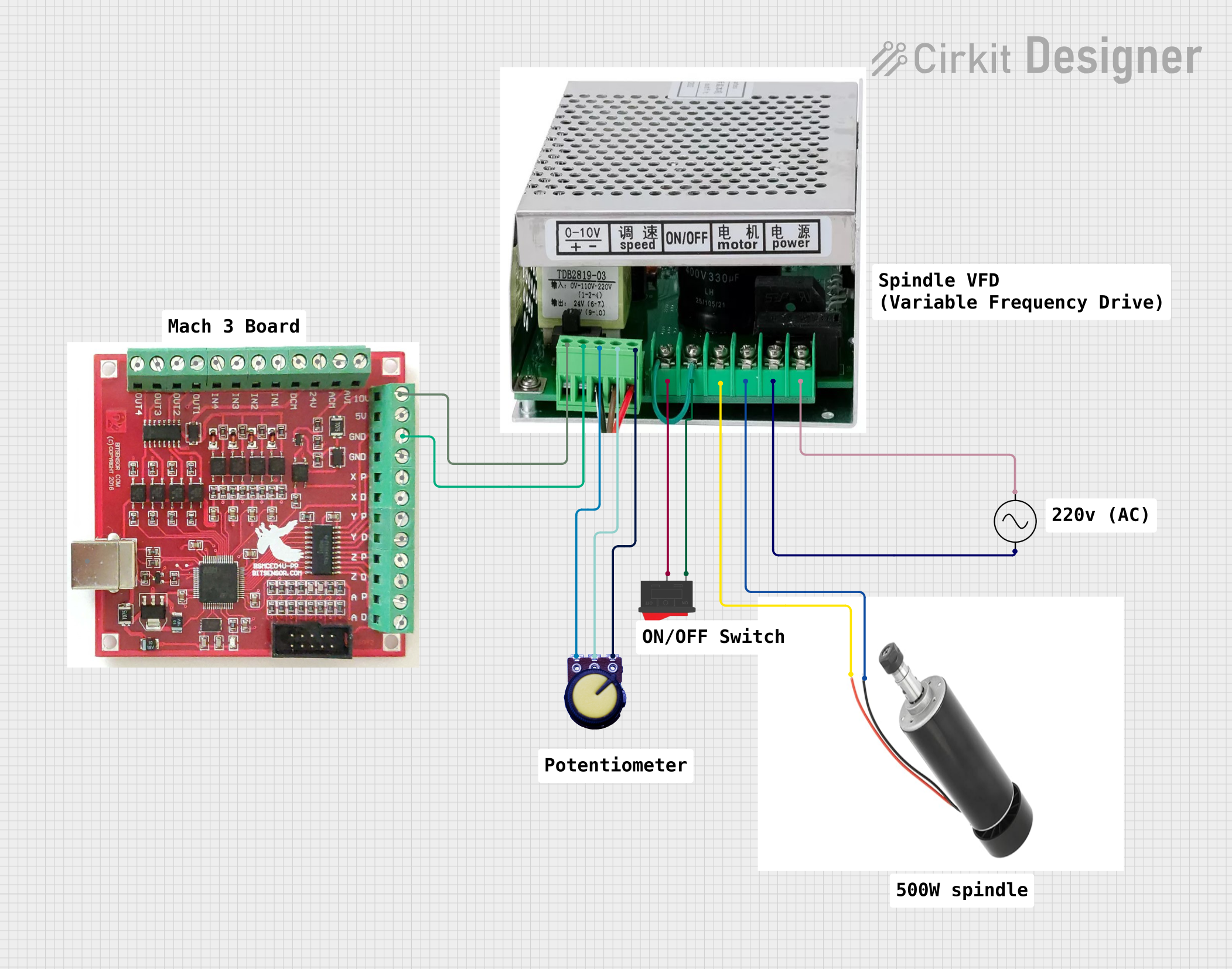
How to Use the Component in a Circuit
Power Connection:
- Connect the input power supply to the L1, L2, and L3 terminals (or L1 and L2 for single-phase).
- Ensure the power supply matches the VFD's input voltage and phase requirements.
Motor Connection:
- Connect the motor's U, V, and W terminals to the corresponding output terminals on the VFD.
- Verify that the motor's voltage and current ratings are compatible with the VFD.
Control Wiring:
- Use the analog input (AI) or digital inputs (DI1, DI2) to control the motor's speed and direction.
- For advanced control, connect a PLC or microcontroller via the RS485 terminals.
Programming:
- Configure the VFD parameters (e.g., motor type, maximum frequency, acceleration time) using the built-in keypad or software interface.
- Refer to the VFD's user manual for detailed programming instructions.
Testing:
- Start the VFD in manual mode and gradually increase the frequency to test motor operation.
- Monitor the motor's performance and ensure there are no abnormal vibrations or noises.
Important Considerations and Best Practices
- Cooling: Ensure adequate ventilation around the VFD to prevent overheating.
- EMI Shielding: Use shielded cables for motor connections to minimize electromagnetic interference.
- Grounding: Properly ground the VFD and motor to ensure safety and reduce electrical noise.
- Overload Protection: Set the VFD's overload protection parameters to match the motor's specifications.
- Startup Checks: Verify all connections and parameter settings before powering on the VFD.
Example: Controlling a VFD with an Arduino UNO
Below is an example of using an Arduino UNO to control a VFD via Modbus RTU over RS485:
#include <ModbusMaster.h>

// Create an instance of the ModbusMaster library
ModbusMaster node;

// Define the RS485 control pin
#define DE_RE_PIN 2

void preTransmission() {
  digitalWrite(DE_RE_PIN, HIGH); // Enable RS485 transmission
}

void postTransmission() {
  digitalWrite(DE_RE_PIN, LOW); // Disable RS485 transmission
}

void setup() {
  // Initialize RS485 control pin
  pinMode(DE_RE_PIN, OUTPUT);
  digitalWrite(DE_RE_PIN, LOW);

  // Initialize Modbus communication
  Serial.begin(9600); // Set baud rate to match VFD
  node.begin(1, Serial); // Set Modbus ID (1 is typical for VFDs)
  node.preTransmission(preTransmission);
  node.postTransmission(postTransmission);
}

void loop() {
  // Example: Set VFD frequency to 50 Hz
  uint8_t result = node.writeSingleRegister(0x2000, 500);
  // 0x2000 is a common address for frequency, 500 = 50.0 Hz

  if (result == node.ku8MBSuccess) {
    Serial.println("Frequency set successfully!");
  } else {
    Serial.println("Failed to set frequency.");
  }

  delay(1000); // Wait 1 second before next command
}
Troubleshooting and FAQs
Common Issues Users Might Face
Motor Does Not Start:
- Cause: Incorrect wiring or parameter settings.
- Solution: Double-check all connections and ensure the start command is properly configured.
Overload or Overcurrent Fault:
- Cause: Motor is drawing more current than the VFD's rated capacity.
- Solution: Verify motor specifications and adjust the VFD's overload protection settings.
VFD Overheating:
- Cause: Inadequate ventilation or excessive load.
- Solution: Ensure proper cooling and reduce the motor load if necessary.
Communication Failure:
- Cause: Incorrect RS485 wiring or baud rate mismatch.
- Solution: Verify the RS485 connections and ensure the baud rate matches the VFD's settings.
Solutions and Tips for Troubleshooting
- Always refer to the VFD's user manual for specific error codes and troubleshooting steps.
- Use a multimeter to check voltage levels and continuity in the wiring.
- If the VFD has a built-in diagnostic tool, use it to identify and resolve issues.
- For advanced troubleshooting, consult the manufacturer's technical support team.