
How to Use Turbidity Module: Examples, Pinouts, and Specs
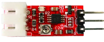
 Design with Turbidity Module in Cirkit Designer
Introduction
The Turbidity Module is a sensor designed to measure the cloudiness or haziness of a liquid, typically water. This cloudiness is caused by suspended particles that scatter light, and the module quantifies this turbidity level. The module outputs either an analog or digital signal, which corresponds to the turbidity of the liquid being measured. It is widely used in water quality monitoring, environmental testing, and industrial applications.
Explore Projects Built with Turbidity Module
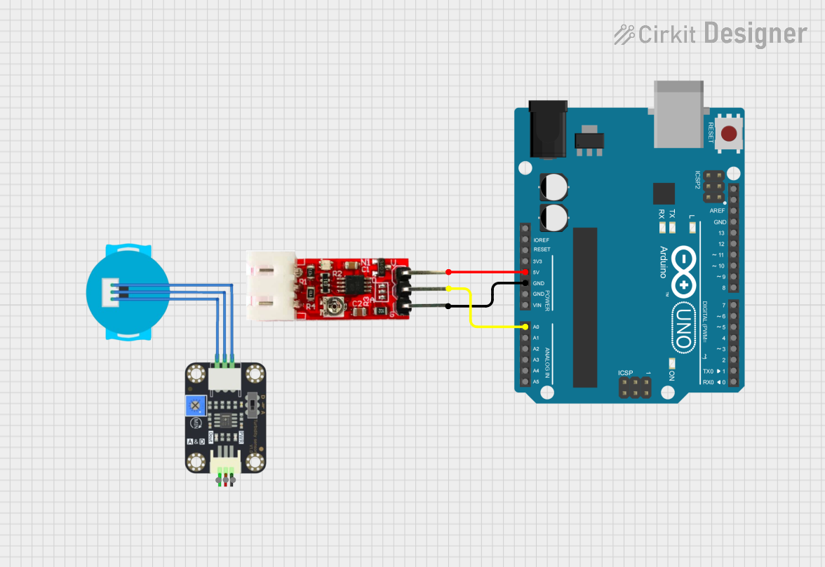 Open Project in Cirkit Designer
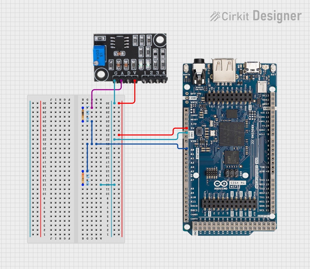 Open Project in Cirkit Designer
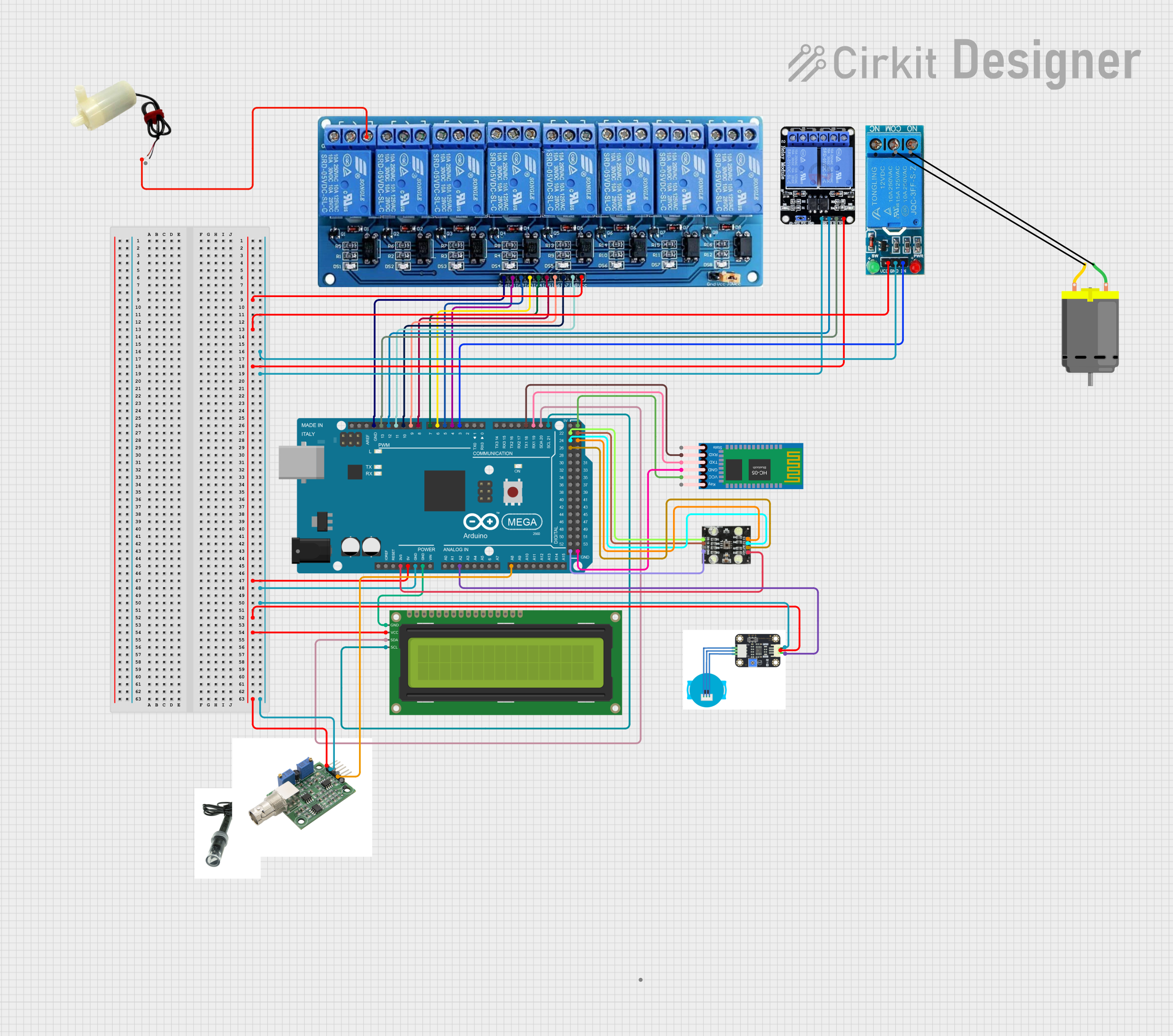 Open Project in Cirkit Designer
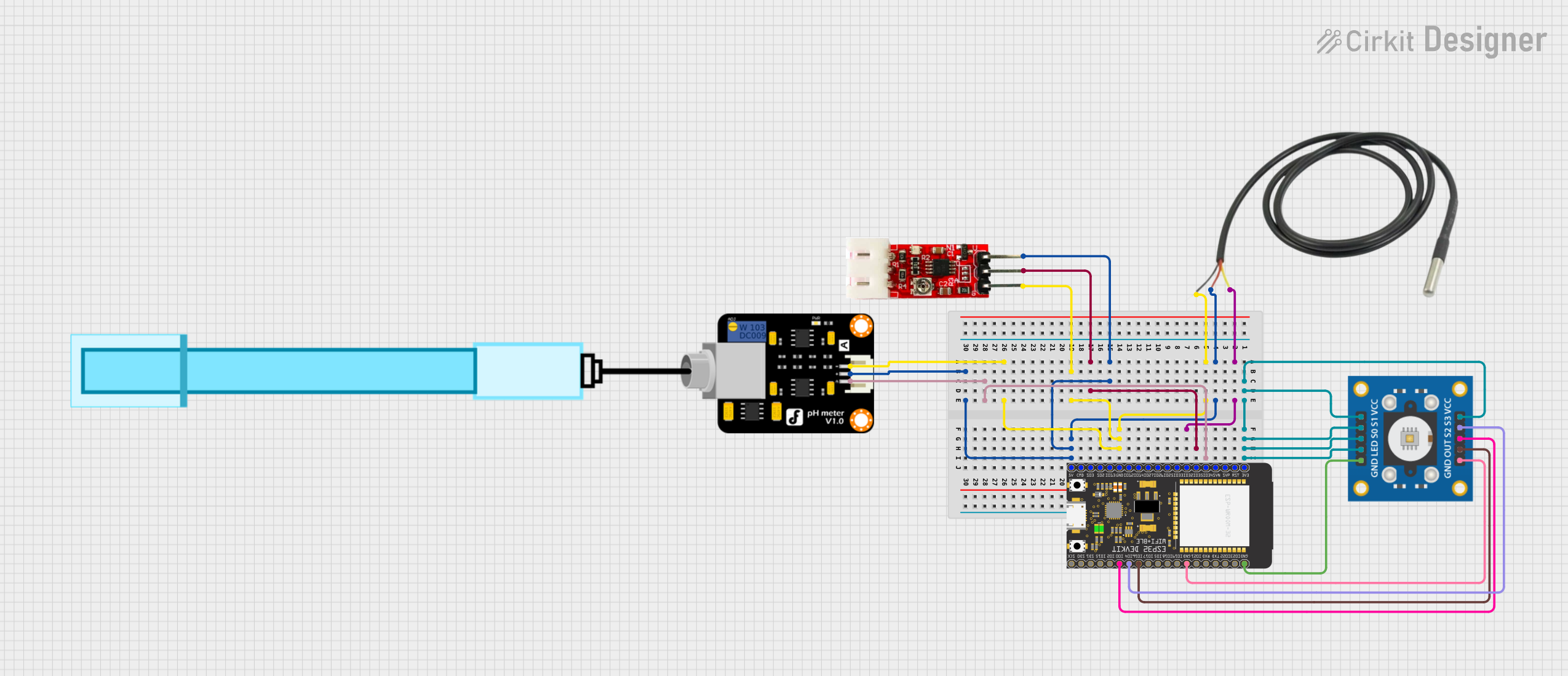 Open Project in Cirkit Designer
Explore Projects Built with Turbidity Module
Open Project in Cirkit DesignerOpen Project in Cirkit DesignerOpen Project in Cirkit DesignerOpen Project in Cirkit DesignerCommon Applications and Use Cases
- Monitoring water quality in aquariums, reservoirs, and natural water bodies
- Industrial process control in water treatment plants
- Environmental testing for pollution levels
- Agricultural irrigation systems to ensure clean water supply
- Educational projects and prototyping with microcontrollers like Arduino
Technical Specifications
The Turbidity Module typically consists of an optical sensor and an onboard signal processing circuit. Below are the key technical details:
| Parameter | Specification |
|---|---|
| Operating Voltage | 5V DC |
| Operating Current | 30mA (typical) |
| Output Type | Analog (0-4.5V) and Digital (High/Low) |
| Detection Range | 0 to 1000 NTU (Nephelometric Turbidity Units) |
| Response Time | < 500ms |
| Operating Temperature | -30°C to 80°C |
| Dimensions | Varies by manufacturer (e.g., 42mm x 32mm) |
Pin Configuration and Descriptions
The Turbidity Module typically has a 4-pin interface. Below is the pinout:
| Pin | Name | Description |
|---|---|---|
| 1 | VCC | Power supply input (5V DC) |
| 2 | GND | Ground connection |
| 3 | AOUT | Analog output signal, proportional to turbidity level |
| 4 | DOUT | Digital output signal, HIGH when turbidity exceeds a preset threshold |
Usage Instructions
How to Use the Turbidity Module in a Circuit
- Power the Module: Connect the
VCCpin to a 5V power source and theGNDpin to ground. - Choose Output Type:
- For analog readings, connect the
AOUTpin to an analog input pin on your microcontroller. - For digital readings, connect the
DOUTpin to a digital input pin. Adjust the onboard potentiometer to set the threshold for the digital output.
- For analog readings, connect the
- Place the Sensor: Submerge the sensor probe in the liquid to be tested. Ensure the probe is clean and free of debris for accurate readings.
- Read the Output:
- For analog output, read the voltage from the
AOUTpin and map it to the turbidity range (e.g., 0-1000 NTU). - For digital output, monitor the
DOUTpin for HIGH or LOW signals based on the preset threshold.
- For analog output, read the voltage from the
Important Considerations and Best Practices
- Calibration: For precise measurements, calibrate the sensor using a known turbidity standard.
- Cleaning: Regularly clean the sensor probe to prevent fouling, which can affect accuracy.
- Placement: Avoid placing the sensor near strong light sources or in turbulent water, as these can interfere with readings.
- Power Supply: Use a stable 5V power source to ensure consistent performance.
Example: Using the Turbidity Module with Arduino UNO
Below is an example of how to interface the Turbidity Module with an Arduino UNO to read analog turbidity values:
// Turbidity Module Example with Arduino UNO
// Reads analog turbidity values and prints them to the Serial Monitor

const int turbidityPin = A0; // Connect AOUT pin of the module to Arduino A0

void setup() {
  Serial.begin(9600); // Initialize serial communication at 9600 baud
  pinMode(turbidityPin, INPUT); // Set the turbidity pin as input
}

void loop() {
  int sensorValue = analogRead(turbidityPin); // Read the analog value from the sensor
  float voltage = sensorValue * (5.0 / 1023.0); // Convert the analog value to voltage
  float turbidity = map(sensorValue, 0, 1023, 0, 1000);
  // Map the sensor value to turbidity range (0-1000 NTU)

  // Print the results to the Serial Monitor
  Serial.print("Analog Value: ");
  Serial.print(sensorValue);
  Serial.print(" | Voltage: ");
  Serial.print(voltage);
  Serial.print("V | Turbidity: ");
  Serial.print(turbidity);
  Serial.println(" NTU");

  delay(1000); // Wait for 1 second before the next reading
}
Troubleshooting and FAQs
Common Issues and Solutions
No Output Signal:
- Ensure the module is powered correctly (5V to
VCCand ground toGND). - Check all connections for loose wires or poor soldering.
- Ensure the module is powered correctly (5V to
Inaccurate Readings:
- Clean the sensor probe to remove any debris or fouling.
- Calibrate the sensor using a known turbidity standard.
Digital Output Always HIGH or LOW:
- Adjust the onboard potentiometer to set an appropriate threshold.
- Verify that the liquid's turbidity is within the sensor's detection range.
Fluctuating Readings:
- Ensure the sensor is not exposed to strong ambient light or placed in turbulent water.
- Use a stable power supply to minimize noise.
FAQs
Q: Can the Turbidity Module measure other liquids besides water?
A: Yes, it can measure the turbidity of other transparent liquids, but the calibration may need adjustment for accurate results.
Q: How do I calibrate the sensor?
A: Use a liquid with a known turbidity value (e.g., a calibration solution) and adjust the readings in your code or hardware setup accordingly.
Q: What is the difference between analog and digital output?
A: The analog output provides a continuous voltage proportional to the turbidity level, while the digital output is a binary signal (HIGH/LOW) based on a preset threshold.
Q: Can I use the Turbidity Module with a 3.3V microcontroller?
A: The module is designed for 5V operation. Use a level shifter or voltage divider to interface with 3.3V systems.