
How to Use thermocouple: Examples, Pinouts, and Specs
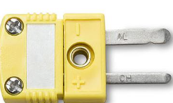
 Design with thermocouple in Cirkit Designer
Introduction
A thermocouple is a temperature sensor that consists of two dissimilar metal wires joined at one end. It generates a voltage that is proportional to the temperature difference between the joined end (hot junction) and the other ends of the wires (cold junction). This voltage can be measured and converted into a temperature reading using appropriate circuitry or microcontrollers.
Thermocouples are widely used in industrial, scientific, and household applications due to their simplicity, durability, and ability to measure a wide range of temperatures. Common use cases include:
- Industrial temperature monitoring in furnaces, kilns, and engines.
- Scientific experiments requiring precise temperature measurements.
- Household appliances like ovens and water heaters.
- HVAC systems for environmental temperature control.
Explore Projects Built with thermocouple
 Open Project in Cirkit Designer
 Open Project in Cirkit Designer
 Open Project in Cirkit Designer
 Open Project in Cirkit Designer
Explore Projects Built with thermocouple
Open Project in Cirkit DesignerOpen Project in Cirkit DesignerOpen Project in Cirkit DesignerOpen Project in Cirkit DesignerTechnical Specifications
Thermocouples come in various types (e.g., Type K, J, T, E), each with different characteristics. Below are general specifications for a Type K thermocouple, one of the most commonly used types:
| Parameter | Specification |
|---|---|
| Temperature Range | -200°C to 1,260°C |
| Accuracy | ±2.2°C or ±0.75% of reading (whichever is greater) |
| Sensitivity | ~41 µV/°C |
| Wire Material | Chromel (Nickel-Chromium) and Alumel (Nickel-Aluminum) |
| Output Voltage Range | ~0 mV to 54.9 mV (over full temperature range) |
| Response Time | Typically 0.5 to 5 seconds (depends on probe design) |
Pin Configuration and Descriptions
Thermocouples do not have traditional "pins" but consist of two wires. The wire configuration is as follows:
| Wire | Description |
|---|---|
| Positive (+) | Chromel wire (usually colored yellow for Type K) |
| Negative (-) | Alumel wire (usually colored red for Type K) |
Note: The color coding may vary by region, so always refer to the manufacturer's datasheet.
Usage Instructions
How to Use a Thermocouple in a Circuit
Connect the Thermocouple to an Amplifier or ADC:
Thermocouples produce very small voltages, so an amplifier (e.g., MAX31855 or MAX6675) is typically required to amplify the signal and convert it into a digital format.Cold Junction Compensation:
Since thermocouples measure the temperature difference between the hot and cold junctions, cold junction compensation is necessary to determine the absolute temperature. Most thermocouple amplifiers include this feature.Connect to a Microcontroller:
The amplified signal can be read by a microcontroller (e.g., Arduino UNO) to calculate the temperature.Power Supply:
Ensure the amplifier module is powered correctly (e.g., 3.3V or 5V, depending on the module).
Example: Using a Type K Thermocouple with Arduino UNO
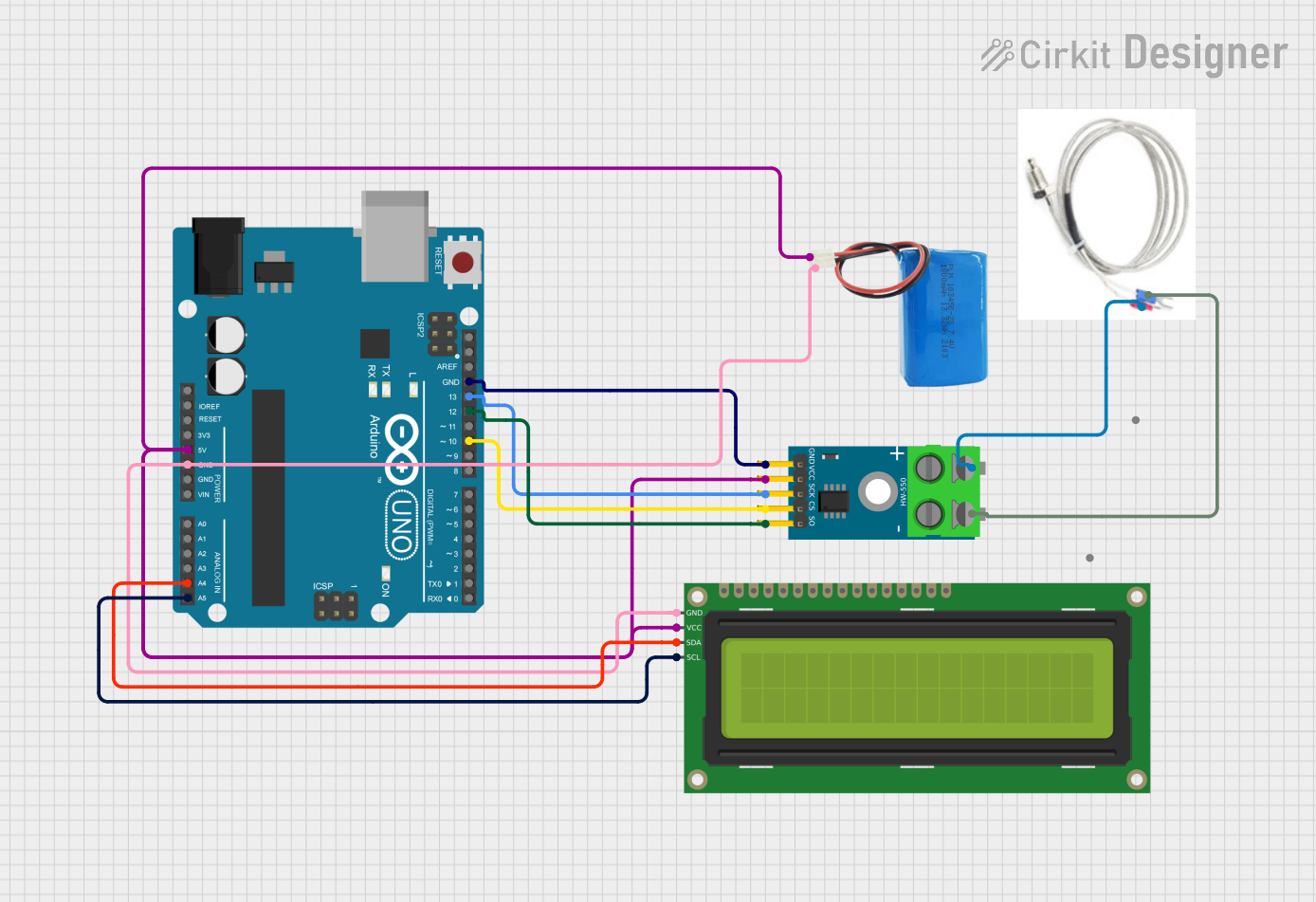
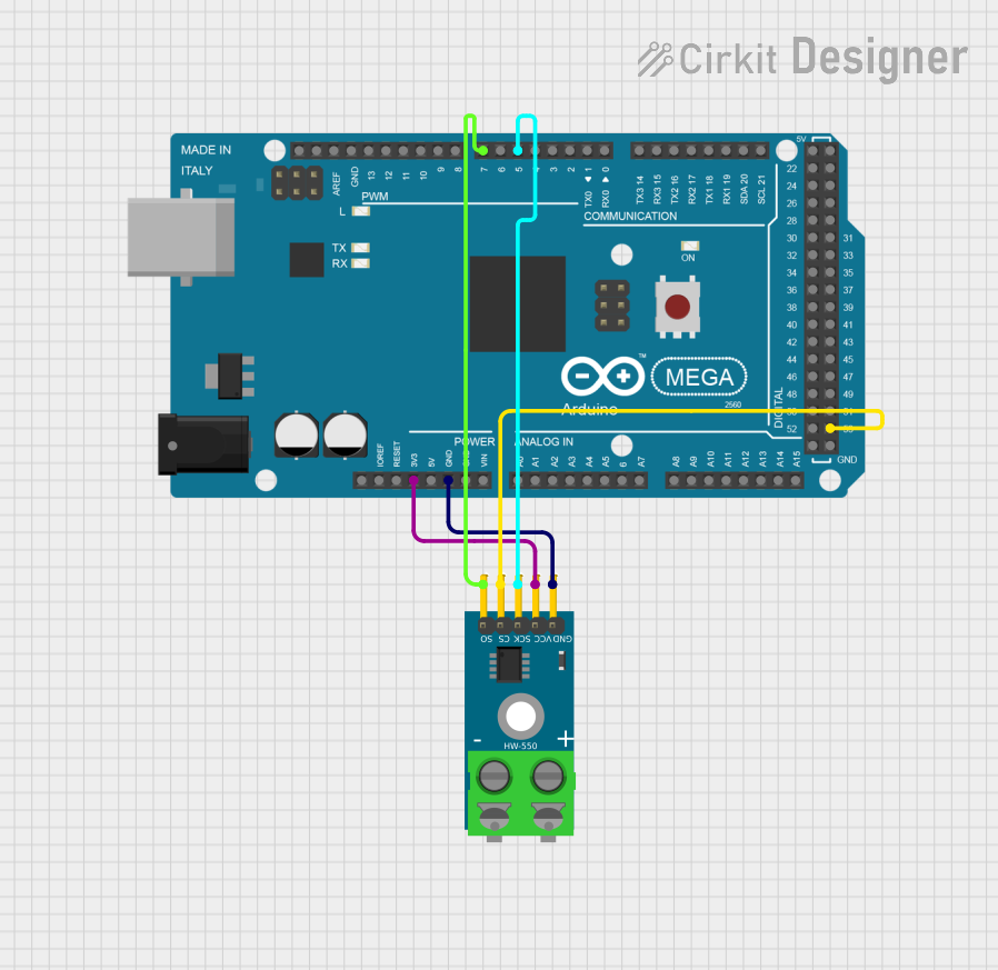
Below is an example of interfacing a Type K thermocouple with an Arduino UNO using the MAX6675 amplifier module:
Circuit Connections
- Connect the thermocouple wires to the MAX6675 module (positive to T+ and negative to T-).
- Connect the MAX6675 module to the Arduino as follows:
- VCC to 5V
- GND to GND
- SCK to Pin 13
- CS to Pin 10
- SO to Pin 12
Arduino Code
#include <SPI.h>
#include "Adafruit_MAX31855.h"

// Define MAX6675 pins
#define DO_PIN 12  // Data Out pin
#define CS_PIN 10  // Chip Select pin
#define CLK_PIN 13 // Clock pin

// Create MAX31855 object
Adafruit_MAX31855 thermocouple(CLK_PIN, CS_PIN, DO_PIN);

void setup() {
  Serial.begin(9600);
  Serial.println("Thermocouple Test");

  // Check if the thermocouple is connected
  if (!thermocouple.begin()) {
    Serial.println("Error: Thermocouple not detected. Check connections.");
    while (1); // Halt execution
  }
}

void loop() {
  // Read temperature in Celsius
  double temperature = thermocouple.readCelsius();

  // Check for errors
  if (isnan(temperature)) {
    Serial.println("Error: Failed to read temperature.");
  } else {
    Serial.print("Temperature: ");
    Serial.print(temperature);
    Serial.println(" °C");
  }

  delay(1000); // Wait 1 second before next reading
}
Important Considerations and Best Practices
- Shielding: Use shielded cables to minimize noise interference, especially in industrial environments.
- Calibration: Regularly calibrate the thermocouple for accurate readings.
- Probe Selection: Choose a thermocouple type and probe design suitable for the temperature range and environment.
- Polarity: Ensure correct polarity when connecting the thermocouple wires to the amplifier.
Troubleshooting and FAQs
Common Issues
No Temperature Reading:
- Check the connections between the thermocouple, amplifier, and microcontroller.
- Verify that the thermocouple is not damaged or broken.
Inaccurate Readings:
- Ensure proper cold junction compensation.
- Check for loose or corroded connections.
- Verify that the thermocouple type matches the amplifier configuration.
Fluctuating Readings:
- Minimize electrical noise by using shielded cables.
- Ensure the thermocouple wires are not near high-power devices or motors.
FAQs
Q: Can I extend the thermocouple wires?
A: Yes, but use thermocouple extension wires made of the same materials as the original wires to avoid introducing errors.
Q: What is cold junction compensation?
A: It is the process of accounting for the temperature at the cold junction (where the thermocouple connects to the amplifier) to calculate the absolute temperature at the hot junction.
Q: Can I use a thermocouple without an amplifier?
A: It is not recommended, as the voltage generated by a thermocouple is very small and requires amplification for accurate measurement.
Q: How do I choose the right thermocouple type?
A: Consider the temperature range, accuracy requirements, and environmental conditions (e.g., corrosive or high-pressure environments). Type K is a good general-purpose choice.