How to Use UPS CARGADOR RAPIDO 5V: Examples, Pinouts, and Specs
Introduction
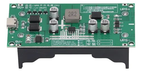
The UPS CARGADOR RAPIDO 5V by THS is a rapid charger designed to deliver a stable 5V output, making it ideal for charging devices in various applications. It is commonly integrated into uninterruptible power supply (UPS) systems to ensure continuous power delivery during outages. This component is highly efficient, compact, and reliable, making it suitable for both consumer electronics and industrial systems.
Explore Projects Built with UPS CARGADOR RAPIDO 5V


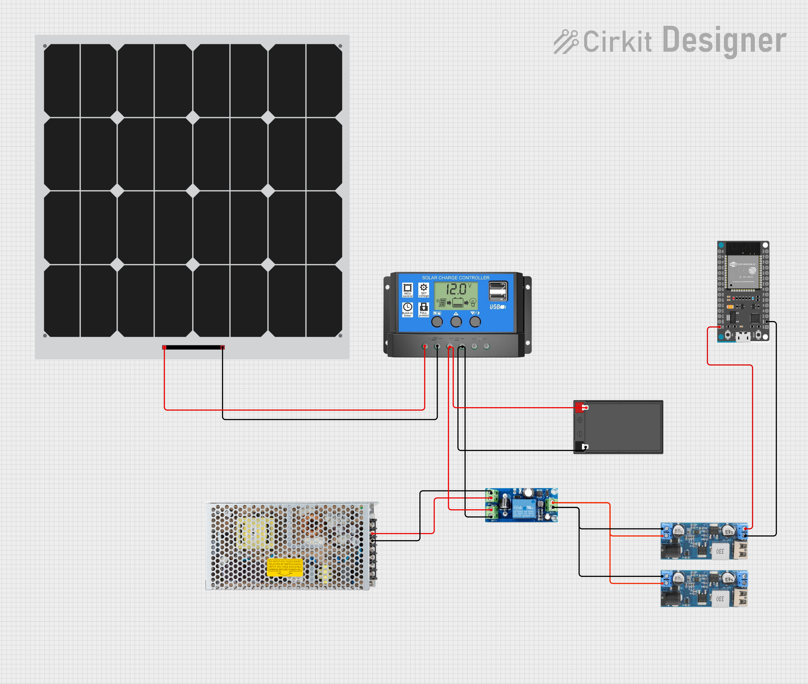
Explore Projects Built with UPS CARGADOR RAPIDO 5V
Common Applications and Use Cases
- Charging mobile devices, IoT devices, and small electronics.
- Integration into UPS systems for backup power.
- Powering low-voltage circuits and microcontrollers.
- Use in emergency power systems to maintain device functionality during outages.
Technical Specifications
The following table outlines the key technical details of the UPS CARGADOR RAPIDO 5V:
| Parameter | Value |
|---|---|
| Input Voltage Range | 100V - 240V AC |
| Output Voltage | 5V DC |
| Output Current | Up to 2.4A |
| Power Rating | 12W |
| Efficiency | ≥ 85% |
| Operating Temperature | -10°C to 50°C |
| Dimensions | 50mm x 30mm x 20mm |
| Weight | 40g |
Pin Configuration and Descriptions
The UPS CARGADOR RAPIDO 5V typically has the following pin configuration:
| Pin Name | Description |
|---|---|
| AC IN (L) | Live input for AC power (100V - 240V). |
| AC IN (N) | Neutral input for AC power. |
| GND | Ground connection for the DC output. |
| +5V OUT | Positive 5V DC output for powering or charging loads. |
Usage Instructions
How to Use the Component in a Circuit
Connect the AC Input:
- Attach the AC IN (L) and AC IN (N) pins to the live and neutral wires of the AC power source, respectively.
- Ensure proper insulation and safety precautions when handling AC connections.
Connect the DC Output:
- Use the +5V OUT pin to supply power to your load (e.g., a device or circuit requiring 5V).
- Connect the GND pin to the ground of your load.
Verify Connections:
- Double-check all connections to ensure they are secure and correct.
- Use a multimeter to confirm the output voltage is 5V before connecting sensitive devices.
Power On:
- Once all connections are verified, power on the AC source. The component will regulate the input and provide a stable 5V output.
Important Considerations and Best Practices
- Heat Management: Ensure adequate ventilation around the component to prevent overheating, especially when operating near the maximum current rating.
- Load Compatibility: Do not exceed the maximum output current of 2.4A to avoid damage to the component or connected devices.
- Safety Precautions: Always handle AC connections with care and ensure proper insulation to prevent electric shock.
- Testing: Before connecting sensitive devices, test the output voltage and current using a multimeter to ensure proper operation.
Example: Using with an Arduino UNO
The UPS CARGADOR RAPIDO 5V can be used to power an Arduino UNO. Below is an example of how to connect it:
- Connect the +5V OUT pin to the Arduino's 5V pin.
- Connect the GND pin to the Arduino's GND pin.
Here is a simple Arduino sketch to blink an LED while powered by the UPS CARGADOR RAPIDO 5V:
// This sketch blinks an LED connected to pin 13 of the Arduino UNO.
// Ensure the UPS CARGADOR RAPIDO 5V is properly connected to the Arduino.

void setup() {
  pinMode(13, OUTPUT); // Set pin 13 as an output pin
}

void loop() {
  digitalWrite(13, HIGH); // Turn the LED on
  delay(1000);            // Wait for 1 second
  digitalWrite(13, LOW);  // Turn the LED off
  delay(1000);            // Wait for 1 second
}
Troubleshooting and FAQs
Common Issues and Solutions
No Output Voltage:
- Cause: Incorrect AC input connection or no power supply.
- Solution: Verify the AC input connections and ensure the power source is active.
Overheating:
- Cause: Insufficient ventilation or excessive load.
- Solution: Reduce the load to within the rated current (2.4A) and ensure proper airflow around the component.
Device Not Charging:
- Cause: Faulty connections or incompatible device.
- Solution: Check the output voltage and current. Ensure the connected device is compatible with a 5V input.
Intermittent Power Delivery:
- Cause: Loose connections or unstable AC input.
- Solution: Secure all connections and verify the stability of the AC power source.
FAQs
Q: Can this component be used with batteries?
A: The UPS CARGADOR RAPIDO 5V is designed for AC input and provides a regulated 5V DC output. It is not directly compatible with batteries as an input source.
Q: Is it safe to use this component outdoors?
A: No, the component is not weatherproof. It should be used in a dry, indoor environment.
Q: Can I use this to power multiple devices simultaneously?
A: Yes, as long as the total current draw does not exceed 2.4A. Use a proper distribution circuit to connect multiple devices.
Q: What happens if the input voltage exceeds 240V?
A: Exceeding the input voltage range may damage the component. Always ensure the input voltage is within the specified range (100V - 240V AC).