How to Use Adafruit GUVA-S12SD UV Light Sensor: Examples, Pinouts, and Specs
Introduction
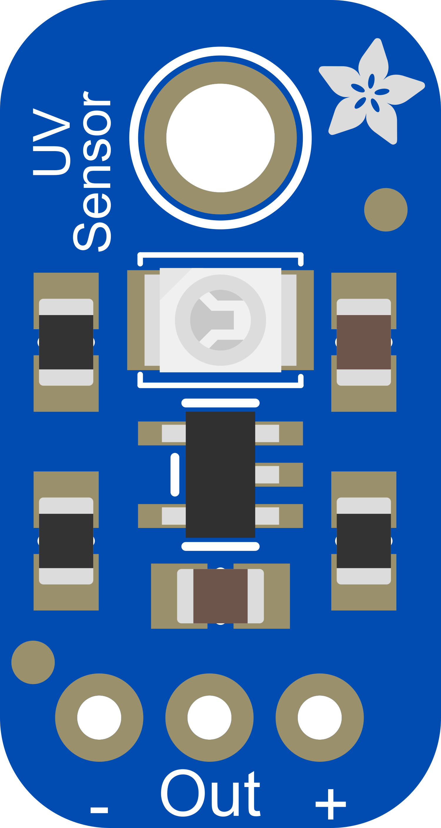
The Adafruit GUVA-S12SD UV Light Sensor is an analog ultraviolet light sensor capable of detecting the intensity of UV radiation, which is commonly associated with sunlight. This sensor is particularly useful for monitoring UV exposure, assessing the UV index for environmental conditions, or controlling UV light sources in various applications such as weather stations, wearable UV detectors, or laboratory equipment.
Explore Projects Built with Adafruit GUVA-S12SD UV Light Sensor
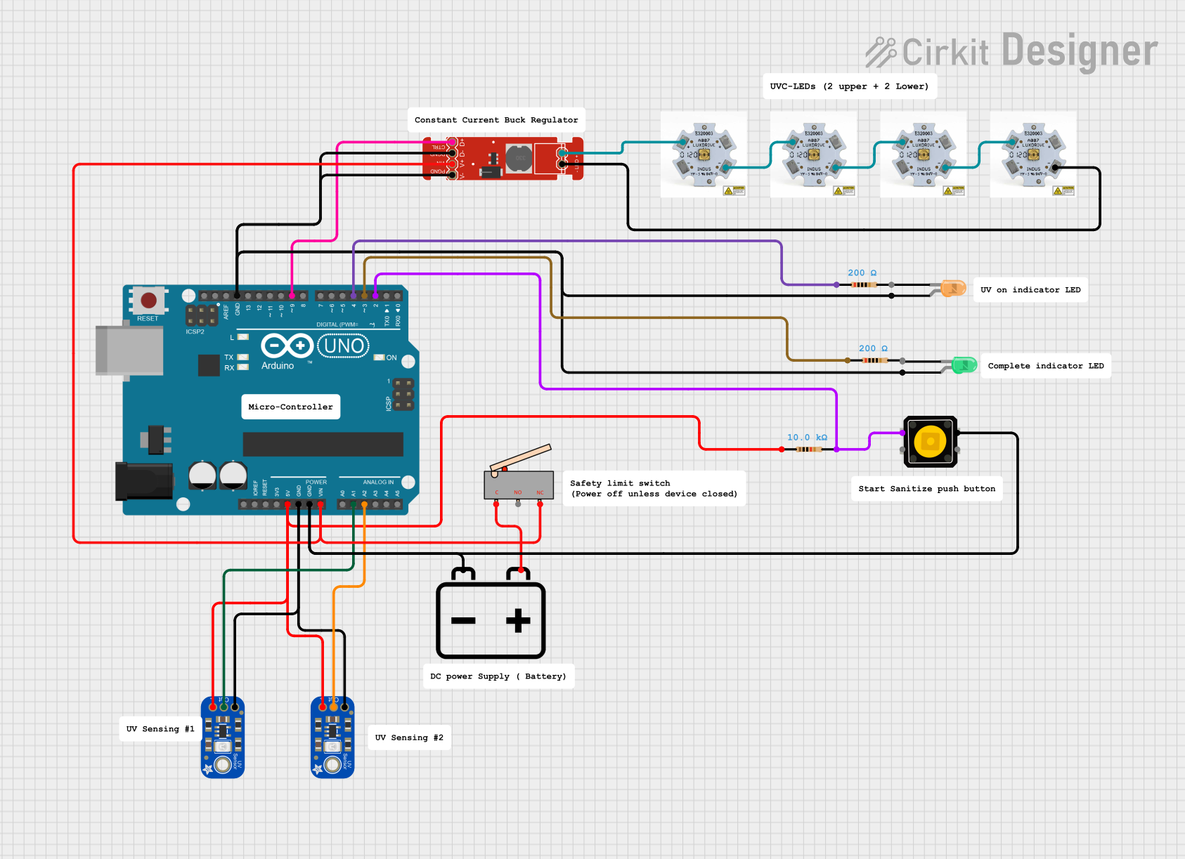
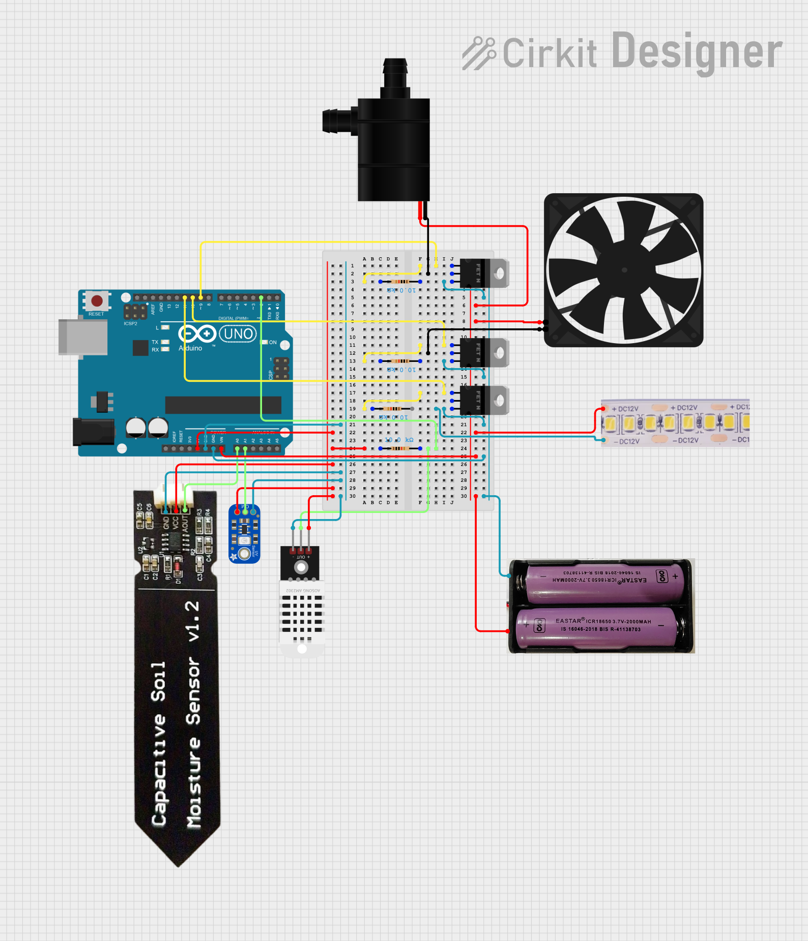

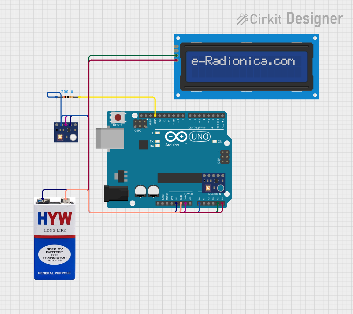
Explore Projects Built with Adafruit GUVA-S12SD UV Light Sensor
Common Applications and Use Cases
- UV Index Monitoring: For weather stations or personal devices that inform users about the current UV exposure level.
- UV Exposure Measurement: In devices that track cumulative UV exposure over time to warn against overexposure.
- UV Light Control: In systems that regulate UV lamps for applications like water purification or sterilization.
Technical Specifications
Key Technical Details
- Spectral Range: 200 nm to 370 nm
- Responsivity: 0.1 to 1.0 µW/cm²/nm
- Operating Voltage: 2.5V to 5.5V
- Output Voltage: 0V to 1V (linear relationship with UV intensity)
- Operating Current: 0.31 mA (typical)
Pin Configuration and Descriptions
| Pin Number | Name | Description |
|---|---|---|
| 1 | VCC | Power supply (2.5V to 5.5V) |
| 2 | GND | Ground connection |
| 3 | OUT | Analog UV intensity output |
Usage Instructions
How to Use the Component in a Circuit
- Power Connection: Connect the VCC pin to a 2.5V to 5.5V power supply and the GND pin to the ground.
- Signal Reading: Connect the OUT pin to an analog input on your microcontroller to read the UV intensity.
- Calibration: Use a known UV light source to calibrate the sensor output if precise measurements are required.
Important Considerations and Best Practices
- Voltage Levels: Ensure that the power supply voltage does not exceed the recommended range to prevent damage.
- Analog-to-Digital Conversion: The microcontroller should have an ADC (Analog-to-Digital Converter) to interpret the analog signal.
- Interference: Avoid placing the sensor near sources of UV light other than the one being measured to prevent false readings.
- Direct Sunlight: When measuring natural sunlight, be aware that the sensor's reading may vary depending on the angle of exposure to the sun.
Example Code for Arduino UNO
// Define the analog pin connected to the sensor
const int uvSensorPin = A0;

void setup() {
  // Initialize serial communication at 9600 baud rate
  Serial.begin(9600);
}

void loop() {
  // Read the analog value from the sensor
  int sensorValue = analogRead(uvSensorPin);

  // Convert the analog value to voltage (assuming a 5V Arduino)
  float voltage = sensorValue * (5.0 / 1023.0);

  // Print the voltage to the Serial Monitor
  Serial.print("UV Sensor Voltage: ");
  Serial.println(voltage);

  // Delay for a bit before reading again
  delay(200);
}
Troubleshooting and FAQs
Common Issues Users Might Face
- Inaccurate Readings: If the sensor provides inconsistent or inaccurate readings, ensure that it is not being affected by other light sources and that it is properly calibrated.
- No Output: Verify that the sensor is correctly powered and that all connections are secure. Also, check if the ADC pin on the microcontroller is functioning properly.
Solutions and Tips for Troubleshooting
- Calibration: Use a UV light source with a known intensity to calibrate the sensor's output.
- Connections: Double-check all connections, including power and ground, for any loose wires or bad solder joints.
- Serial Monitor: Use the Serial Monitor to debug and monitor the sensor's output in real-time.
FAQs
Q: Can the sensor detect UV light through glass? A: Most glass types block a significant portion of UV light. For accurate measurements, the sensor should have direct exposure to the UV source without glass interference.
Q: What is the lifespan of the sensor? A: The sensor's lifespan can vary based on usage, but it is generally designed for long-term performance with minimal degradation over time when used within its specified limits.
Q: How do I convert the voltage reading to UV Index? A: Converting voltage to UV Index requires calibration with a known UV source and may involve specific calculations based on the sensor's responsivity. Consult the sensor's datasheet and relevant UV Index standards for guidance.