Cirkit Designer LogoCirkit DesignerYour all-in-one circuit design IDE Launch Cirkit Designer App

How to Use Solar Power Management Module, for 6V~24V Solar Panel: Examples, Pinouts, and Specs

Image of Solar Power Management Module, for 6V~24V Solar PanelDesign with Solar Power Management Module, for 6V~24V Solar Panel in Cirkit Designer

Introduction

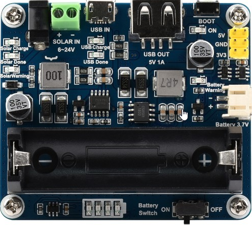
The Waveshare Solar Power Manager is a versatile device designed to optimize the performance of solar panels by regulating voltage and current. It ensures efficient energy conversion and storage for systems operating within a voltage range of 6V to 24V. This module is ideal for renewable energy projects, enabling seamless integration of solar power into electronic systems.

Explore Projects Built with Solar Power Management Module, for 6V~24V Solar Panel

Use Cirkit Designer to design, explore, and prototype these projects online. Some projects support real-time simulation. Click "Open Project" to start designing instantly!
Image of Solar-Powered UPS with Multiple Battery Management: A project utilizing Solar Power Management Module, for 6V~24V Solar Panel in a practical application
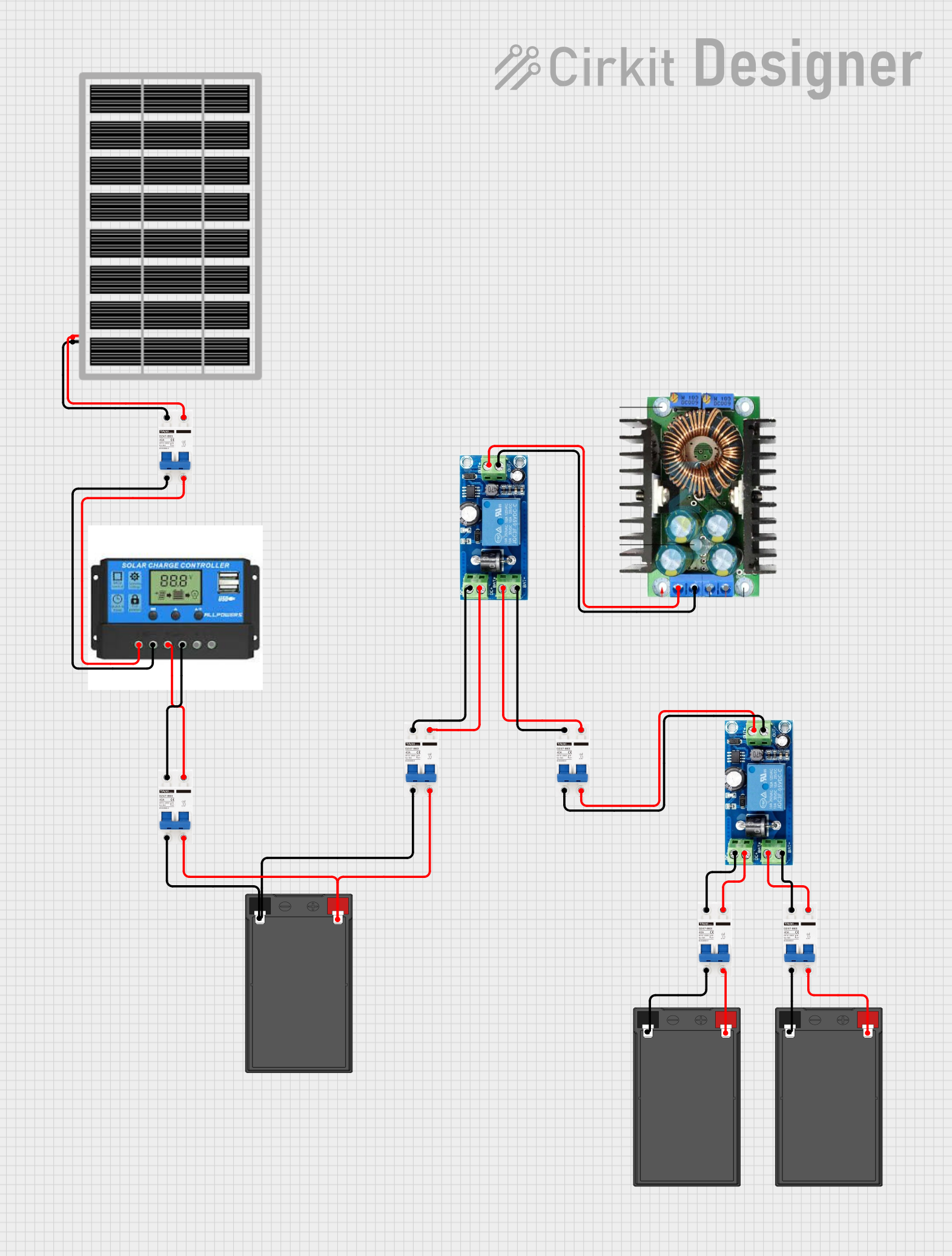
Solar-Powered UPS with Multiple Battery Management

This circuit is designed to integrate a solar power system with multiple 12V batteries and a UPS module for uninterrupted power supply. The solar panel charges the batteries through a charge controller, which is protected by DC MCBs. The UPS modules are connected to the batteries and provide a regulated DC output, which is then adjusted by an XL4016 DC-DC converter module.

Open Project in Cirkit Designer

Common Applications and Use Cases

Technical Specifications

The following table outlines the key technical details of the Solar Power Manager:

Parameter Value
Input Voltage Range 6V to 24V
Output Voltage (USB) 5V ± 0.1V
Output Current (USB) Up to 2.5A
Battery Charging Voltage 4.2V
Battery Charging Current 1A (default, adjustable)
Efficiency Up to 96%
Operating Temperature -40°C to 85°C
Dimensions 65mm × 56mm

Pin Configuration and Descriptions

The module features several input/output pins and connectors for solar panels, batteries, and load devices. Below is the pin configuration:

Pin/Connector Description
SOLAR IN Input for the solar panel (6V to 24V).
BAT IN Connection for a rechargeable battery (e.g., Li-ion or LiPo).
USB OUT 5V regulated output for powering USB devices.
LOAD OUT Output for powering external devices directly from the battery or solar panel.
CHG LED Indicates battery charging status (ON = charging, OFF = fully charged).
PWR LED Indicates power status (ON = power available).
EN (Enable) Enable/disable the module's output.

Usage Instructions

How to Use the Component in a Circuit

  1. Connect the Solar Panel: Attach a solar panel (6V to 24V) to the SOLAR IN connector. Ensure the panel's voltage and current ratings are within the module's specifications.
  2. Connect the Battery: Attach a rechargeable battery to the BAT IN connector. The module supports Li-ion or LiPo batteries with a nominal voltage of 3.7V.
  3. Connect the Load: Use the LOAD OUT or USB OUT connectors to power external devices. The USB OUT provides a regulated 5V output, while LOAD OUT directly supplies power from the battery or solar panel.
  4. Enable the Module: Use the EN pin to enable or disable the output. By default, the module is enabled.

Important Considerations and Best Practices

Example: Using with an Arduino UNO

The Solar Power Manager can be used to power an Arduino UNO via its USB OUT port. Below is an example code snippet for a solar-powered Arduino project:

/*
  Solar Power Manager Example
  This code reads data from a temperature sensor and sends it to the serial monitor.
  The Arduino UNO is powered by the Waveshare Solar Power Manager.
*/

const int sensorPin = A0; // Analog pin connected to the temperature sensor
float voltage;            // Variable to store sensor voltage
float temperature;        // Variable to store calculated temperature

void setup() {
  Serial.begin(9600); // Initialize serial communication
  pinMode(sensorPin, INPUT); // Set sensor pin as input
}

void loop() {
  voltage = analogRead(sensorPin) * (5.0 / 1023.0); // Convert ADC value to voltage
  temperature = (voltage - 0.5) * 100.0; // Convert voltage to temperature (Celsius)
  
  // Print temperature to the serial monitor
  Serial.print("Temperature: ");
  Serial.print(temperature);
  Serial.println(" °C");
  
  delay(1000); // Wait 1 second before the next reading
}

Troubleshooting and FAQs

Common Issues and Solutions

  1. No Output Power

    • Cause: Solar panel voltage is too low or disconnected.
    • Solution: Ensure the solar panel is properly connected and its voltage is within the 6V to 24V range.
  2. Battery Not Charging

    • Cause: Incompatible battery or incorrect connection.
    • Solution: Verify the battery type (Li-ion or LiPo) and ensure correct polarity.
  3. Overheating

    • Cause: Excessive load or poor ventilation.
    • Solution: Reduce the load or improve ventilation around the module.
  4. LED Indicators Not Working

    • Cause: Faulty connections or damaged LEDs.
    • Solution: Check all connections and replace the module if necessary.

FAQs