How to Use Mechanical End Stop: Examples, Pinouts, and Specs
Introduction
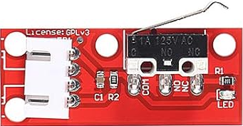
The Mechanical End Stop (Manufacturer: ALMOCN, Part ID: AL10142) is a physical device designed to limit the movement of a mechanism, ensuring it does not exceed a predetermined range. It is commonly used in CNC machines, 3D printers, and other automated systems to provide precise control over motion. The end stop typically consists of a switch that is triggered when a moving part makes contact, sending a signal to the control system to halt further motion.
Explore Projects Built with Mechanical End Stop
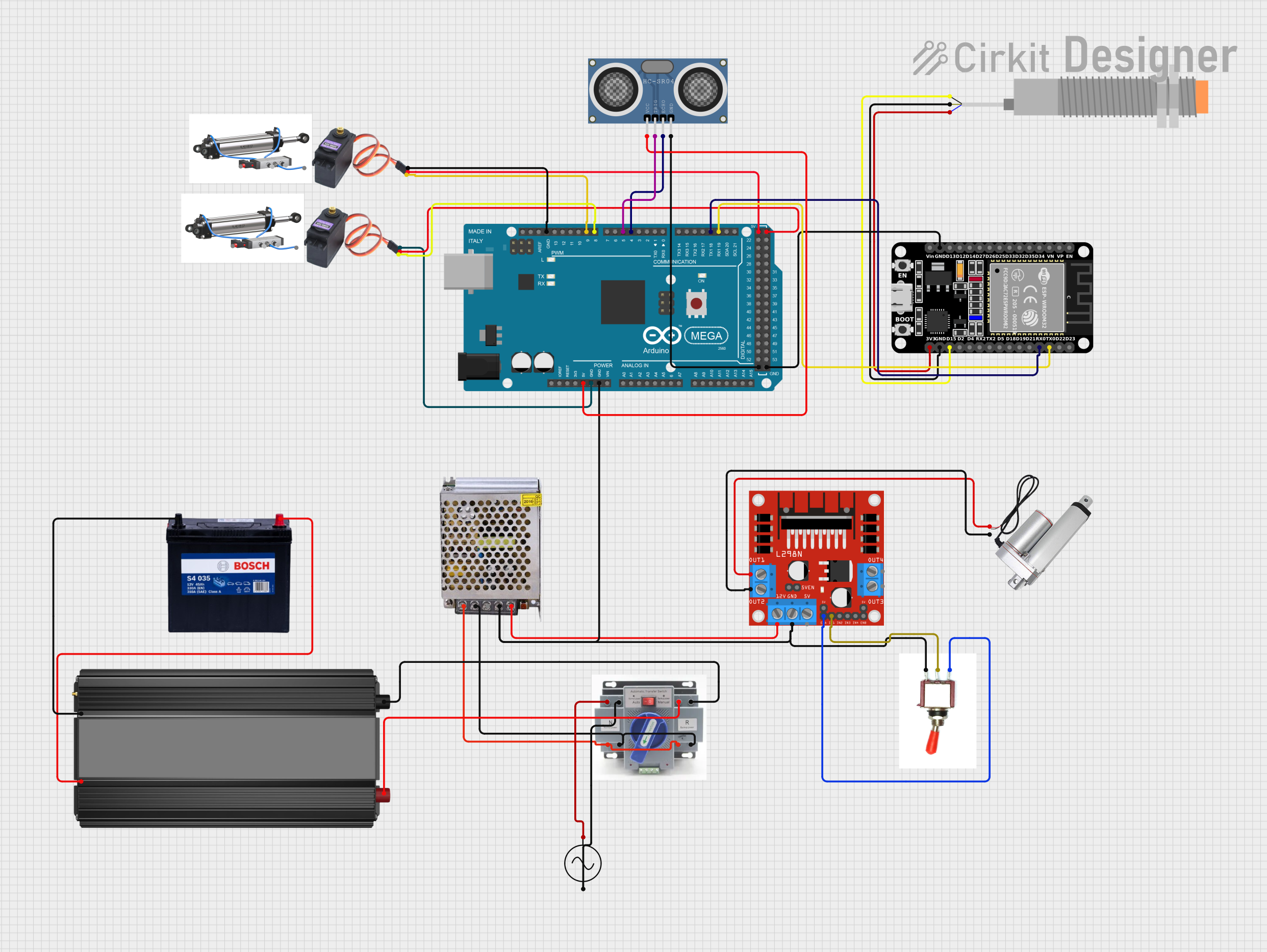
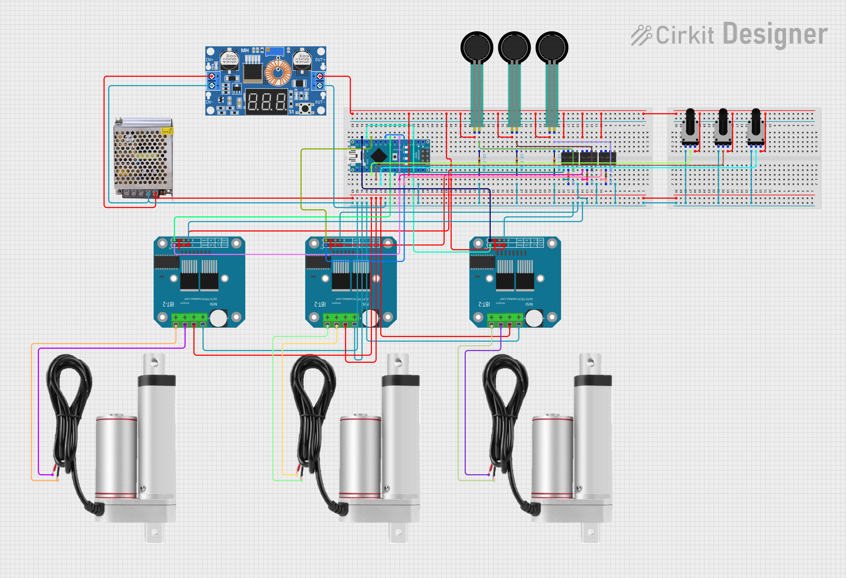

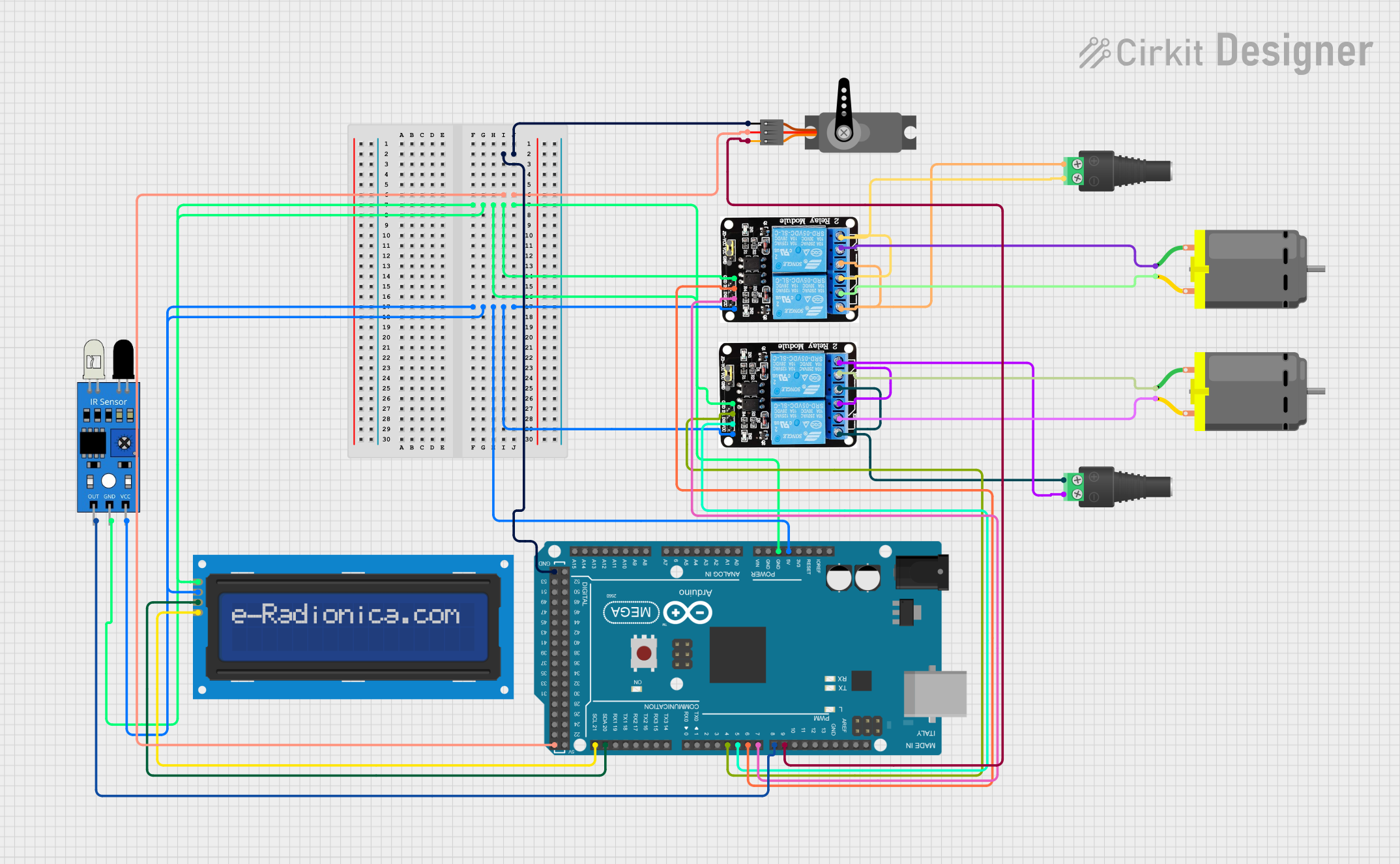
Explore Projects Built with Mechanical End Stop
Common Applications
- 3D Printers: To define the home position and prevent over-travel of axes.
- CNC Machines: To ensure safe operation by limiting axis movement.
- Robotics: For position detection and motion control.
- Automated Systems: To provide feedback for precise mechanical positioning.
Technical Specifications
Key Technical Details
- Manufacturer: ALMOCN
- Part ID: AL10142
- Operating Voltage: 5V DC
- Switch Type: Normally Open (NO)
- Contact Resistance: ≤ 50 mΩ
- Insulation Resistance: ≥ 100 MΩ
- Mechanical Durability: 1,000,000 cycles
- Cable Length: 1 meter (pre-soldered with connector)
- Connector Type: 3-pin Dupont (compatible with most microcontrollers)
- Mounting Holes: 2 x M3 holes for secure attachment
Pin Configuration and Descriptions
The Mechanical End Stop has a 3-pin connector with the following pinout:
| Pin | Name | Description |
|---|---|---|
| 1 | Signal (S) | Outputs a HIGH or LOW signal depending on the switch state (triggered or idle). |
| 2 | VCC | Power supply input (5V DC). |
| 3 | GND | Ground connection. |
Usage Instructions
How to Use the Mechanical End Stop in a Circuit
Wiring:
- Connect the Signal (S) pin to a digital input pin on your microcontroller (e.g., Arduino UNO).
- Connect the VCC pin to a 5V power source.
- Connect the GND pin to the ground of your circuit.
Mounting:
- Secure the end stop to the desired location using the provided M3 mounting holes.
- Ensure the moving part of your mechanism makes contact with the switch lever when it reaches the limit.
Testing:
- Power on your system and monitor the signal pin.
- When the switch is triggered, the signal pin should change state (e.g., from HIGH to LOW).
Important Considerations
- Debouncing: Mechanical switches may produce noise or false signals when triggered. Use software debouncing or a capacitor across the signal pin to filter out noise.
- Alignment: Ensure the moving part aligns properly with the switch lever to avoid damage or misalignment.
- Voltage Compatibility: Do not exceed the rated 5V DC operating voltage to prevent damage to the component.
Example Code for Arduino UNO
Below is an example of how to use the Mechanical End Stop with an Arduino UNO:
// Define the pin connected to the Signal (S) pin of the end stop
const int endStopPin = 2; // Digital pin 2

void setup() {
  pinMode(endStopPin, INPUT_PULLUP); // Set pin as input with internal pull-up resistor
  Serial.begin(9600); // Initialize serial communication for debugging
}

void loop() {
  int endStopState = digitalRead(endStopPin); // Read the state of the end stop

  if (endStopState == LOW) {
    // The end stop is triggered (switch closed)
    Serial.println("End Stop Triggered!");
  } else {
    // The end stop is not triggered (switch open)
    Serial.println("End Stop Not Triggered.");
  }

  delay(100); // Small delay to avoid spamming the serial monitor
}
Notes:
- The
INPUT_PULLUPmode ensures the pin is HIGH by default and goes LOW when the switch is triggered. - Adjust the
endStopPinvariable to match the pin you are using on your Arduino.
Troubleshooting and FAQs
Common Issues and Solutions
The end stop does not trigger:
- Check the wiring to ensure all connections are secure and correct.
- Verify that the moving part makes proper contact with the switch lever.
False triggers or noise:
- Add a 0.1 µF capacitor across the signal and ground pins to reduce noise.
- Implement software debouncing in your microcontroller code.
No signal change when triggered:
- Ensure the microcontroller pin is configured as an input.
- Test the end stop with a multimeter to confirm the switch is functioning.
Switch lever gets stuck:
- Inspect the lever for physical damage or debris.
- Ensure proper alignment of the moving part with the switch lever.
FAQs
Q: Can this end stop be used with 3.3V systems?
A: While the end stop is designed for 5V, it may work with 3.3V systems. However, ensure the signal voltage is compatible with your microcontroller.Q: How do I extend the cable length?
A: Use a compatible 3-pin Dupont cable extension or solder additional wires, ensuring proper insulation.Q: Is the end stop waterproof?
A: No, the ALMOCN AL10142 is not waterproof. Avoid using it in environments with high humidity or water exposure.Q: Can I use multiple end stops in one system?
A: Yes, connect each end stop to a separate digital input pin on your microcontroller.
By following this documentation, you can effectively integrate the ALMOCN AL10142 Mechanical End Stop into your projects for reliable motion control and position detection.