Cirkit Designer Logo
Cirkit Designer
Your all-in-one circuit design IDE
Home / 
Component Documentation

How to Use 5V PSU: Examples, Pinouts, and Specs

Image of 5V PSU
Cirkit Designer LogoDesign with 5V PSU in Cirkit Designer

Introduction

A 5V Power Supply Unit (PSU) provides a stable 5-volt output to power electronic circuits and devices, ensuring consistent voltage for reliable operation. It is a fundamental component in electronics, commonly used to power microcontrollers, sensors, LEDs, and other low-voltage devices. The 5V PSU is essential for projects requiring a reliable and regulated power source.

Explore Projects Built with 5V PSU

Use Cirkit Designer to design, explore, and prototype these projects online. Some projects support real-time simulation. Click "Open Project" to start designing instantly!
12V to 5V Power Supply with LED Indicator and Push Switch
Image of Power Supply LVCO: A project utilizing 5V PSU in a practical application
This circuit is a 12V to 5V regulated power supply with an LED indicator. It uses a 5408 diode for reverse polarity protection, an LM340T5 7805 voltage regulator to step down the voltage to 5V, and a push switch to control the LED indicator. The circuit also includes capacitors for filtering and a resistor to limit the current through the LED.
Cirkit Designer LogoOpen Project in Cirkit Designer
Battery-Powered USB Charger with LED Indicator and DC Motor
Image of Copy of Hand Crank mobile charger : A project utilizing 5V PSU in a practical application
This circuit converts AC power to DC using a bridge rectifier and regulates the voltage to 5V with a 7805 voltage regulator. It powers a USB port and indicates power status with an LED, while also providing a charging interface through a multi-charging cable.
Cirkit Designer LogoOpen Project in Cirkit Designer
Dual 5V Power Supply Distribution Circuit with Toggle Switch Control
Image of rfdriver: A project utilizing 5V PSU in a practical application
This circuit consists of two 5V 5A power supplies connected to an AC wall plug point, providing DC output through a 12-way connector. The ground connections from both power supplies are interconnected and also connected to the ground pins of two toggle switches. The DC outputs from the power supplies are separately connected to different pins on the 12-way connector, with each power supply output being switchable via one of the toggle switches.
Cirkit Designer LogoOpen Project in Cirkit Designer
USB-Powered DC Gear Motor with LED Indicator
Image of Hand Crank mobile charger : A project utilizing 5V PSU in a practical application
This circuit appears to be a power supply unit with a bridge rectifier connected to a DC gear motor, indicating it is designed to convert AC to DC power for the motor. An electrolytic capacitor is used for smoothing the DC output, and a 7805 voltage regulator is included to provide a stable 5V output. Additionally, there is an LED with a series resistor, likely serving as a power indicator light.
Cirkit Designer LogoOpen Project in Cirkit Designer

Explore Projects Built with 5V PSU

Use Cirkit Designer to design, explore, and prototype these projects online. Some projects support real-time simulation. Click "Open Project" to start designing instantly!
Image of Power Supply LVCO: A project utilizing 5V PSU in a practical application
12V to 5V Power Supply with LED Indicator and Push Switch
This circuit is a 12V to 5V regulated power supply with an LED indicator. It uses a 5408 diode for reverse polarity protection, an LM340T5 7805 voltage regulator to step down the voltage to 5V, and a push switch to control the LED indicator. The circuit also includes capacitors for filtering and a resistor to limit the current through the LED.
Cirkit Designer LogoOpen Project in Cirkit Designer
Image of Copy of Hand Crank mobile charger : A project utilizing 5V PSU in a practical application
Battery-Powered USB Charger with LED Indicator and DC Motor
This circuit converts AC power to DC using a bridge rectifier and regulates the voltage to 5V with a 7805 voltage regulator. It powers a USB port and indicates power status with an LED, while also providing a charging interface through a multi-charging cable.
Cirkit Designer LogoOpen Project in Cirkit Designer
Image of rfdriver: A project utilizing 5V PSU in a practical application
Dual 5V Power Supply Distribution Circuit with Toggle Switch Control
This circuit consists of two 5V 5A power supplies connected to an AC wall plug point, providing DC output through a 12-way connector. The ground connections from both power supplies are interconnected and also connected to the ground pins of two toggle switches. The DC outputs from the power supplies are separately connected to different pins on the 12-way connector, with each power supply output being switchable via one of the toggle switches.
Cirkit Designer LogoOpen Project in Cirkit Designer
Image of Hand Crank mobile charger : A project utilizing 5V PSU in a practical application
USB-Powered DC Gear Motor with LED Indicator
This circuit appears to be a power supply unit with a bridge rectifier connected to a DC gear motor, indicating it is designed to convert AC to DC power for the motor. An electrolytic capacitor is used for smoothing the DC output, and a 7805 voltage regulator is included to provide a stable 5V output. Additionally, there is an LED with a series resistor, likely serving as a power indicator light.
Cirkit Designer LogoOpen Project in Cirkit Designer

Common Applications and Use Cases

  • Powering microcontrollers such as Arduino, Raspberry Pi, and ESP32.
  • Supplying power to sensors, actuators, and small motors.
  • Driving LEDs, displays, and other low-power electronic components.
  • Providing a stable voltage source for breadboard prototyping.
  • Charging USB-powered devices.

Technical Specifications

The following table outlines the key technical details of a typical 5V PSU:

Parameter Specification
Input Voltage Range 100-240V AC (for AC-DC PSUs)
Output Voltage 5V DC ± 5%
Output Current 500mA to 3A (varies by model)
Power Rating 2.5W to 15W
Efficiency ≥ 80%
Ripple and Noise ≤ 50mV
Protection Features Overcurrent, Overvoltage, Short Circuit

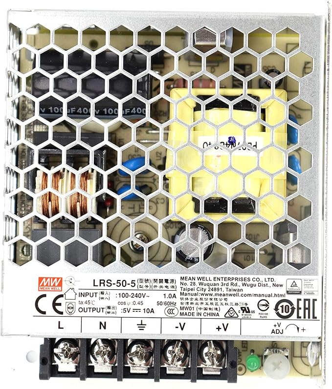
Pin Configuration and Descriptions

For a typical 5V PSU with a DC barrel jack or screw terminal output, the pin configuration is as follows:

Pin Description
+V Positive 5V DC output
GND Ground (0V reference)

For USB-powered 5V PSUs, the pin configuration is:

Pin Description
VBUS Positive 5V DC output
GND Ground (0V reference)
D+ Data line (not used for power)
D- Data line (not used for power)

Usage Instructions

How to Use the 5V PSU in a Circuit

  1. Connect the Input Power Source:
    • For AC-DC PSUs, plug the unit into a standard AC outlet.
    • For USB-powered PSUs, connect the USB cable to a compatible power source (e.g., a USB wall adapter or computer).
  2. Connect the Output Terminals:
    • Identify the positive (+V) and ground (GND) terminals.
    • Connect the +V terminal to the positive rail of your circuit.
    • Connect the GND terminal to the ground rail of your circuit.
  3. Verify Connections:
    • Double-check all connections to ensure proper polarity and avoid short circuits.
  4. Power On:
    • Turn on the PSU (if it has a power switch) or connect it to the input power source.

Important Considerations and Best Practices

  • Check Current Requirements: Ensure the PSU can supply sufficient current for all connected devices. Exceeding the PSU's current rating may cause overheating or shutdown.
  • Avoid Overloading: Do not connect devices that draw more power than the PSU's rated output.
  • Use Proper Wiring: Use wires with appropriate gauge to handle the current without excessive voltage drop.
  • Monitor Heat: If the PSU becomes excessively hot, reduce the load or improve ventilation.
  • Protect Against Short Circuits: Use fuses or circuit breakers to prevent damage in case of a short circuit.

Example: Using a 5V PSU with an Arduino UNO

The 5V PSU can be used to power an Arduino UNO via its VIN pin or USB port. Below is an example of powering an Arduino UNO and blinking an LED:

Circuit Connections

  1. Connect the +V terminal of the PSU to the VIN pin of the Arduino UNO.
  2. Connect the GND terminal of the PSU to the GND pin of the Arduino UNO.
  3. Connect an LED and a 220-ohm resistor to pin 13 of the Arduino UNO.

Arduino Code

// This code blinks an LED connected to pin 13 of the Arduino UNO.
// Ensure the 5V PSU is properly connected to the Arduino.

void setup() {
  pinMode(13, OUTPUT); // Set pin 13 as an output pin
}

void loop() {
  digitalWrite(13, HIGH); // Turn the LED on
  delay(1000);            // Wait for 1 second
  digitalWrite(13, LOW);  // Turn the LED off
  delay(1000);            // Wait for 1 second
}

Troubleshooting and FAQs

Common Issues and Solutions

  1. No Output Voltage:

    • Cause: Input power is not connected or PSU is faulty.
    • Solution: Verify the input power source and check the PSU for damage.
  2. Voltage Drops Under Load:

    • Cause: Load exceeds the PSU's current rating.
    • Solution: Reduce the load or use a higher-rated PSU.
  3. PSU Overheating:

    • Cause: Prolonged operation at maximum load or poor ventilation.
    • Solution: Reduce the load and ensure proper airflow around the PSU.
  4. Devices Not Powering On:

    • Cause: Incorrect wiring or polarity.
    • Solution: Double-check all connections and ensure correct polarity.

FAQs

  • Can I use a 5V PSU to charge USB devices? Yes, as long as the PSU provides sufficient current and has a USB output.

  • What happens if I connect a 3.3V device to a 5V PSU? Connecting a 3.3V device directly to a 5V PSU may damage the device. Use a voltage regulator or level shifter.

  • Is it safe to leave the PSU powered on continuously? Most 5V PSUs are designed for continuous operation, but ensure proper ventilation to prevent overheating.

  • Can I use a 5V PSU to power multiple devices? Yes, as long as the total current draw does not exceed the PSU's rated output.