How to Use OctoAcoplador Module: Examples, Pinouts, and Specs
Introduction
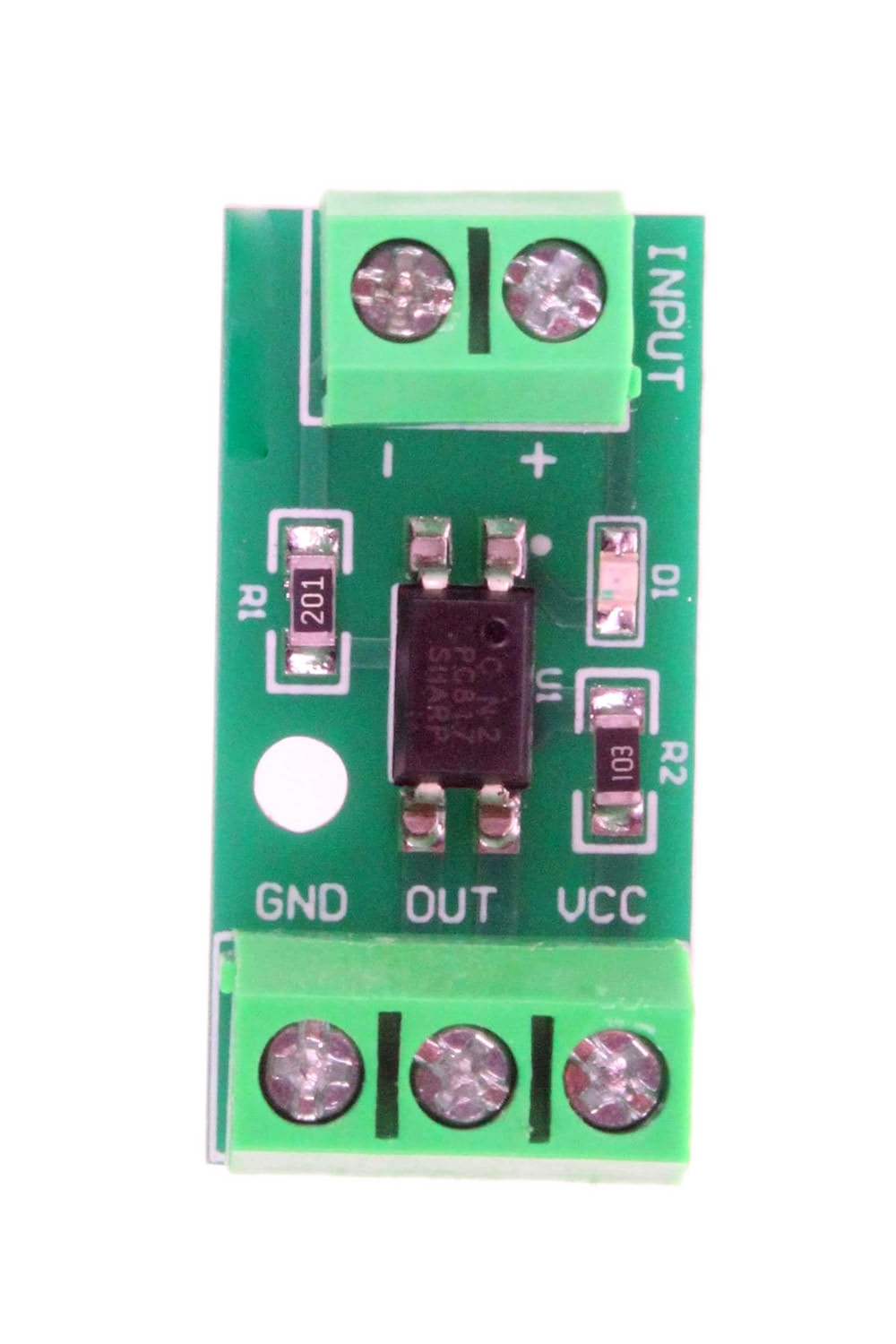
The OctoAcoplador Module is a specialized opto-isolator designed to isolate and control multiple signals simultaneously. It typically integrates eight opto-isolators within a single package, making it ideal for applications requiring the safe interfacing of high-voltage circuits with low-voltage control systems. By using light to transfer signals between its input and output, the module ensures electrical isolation, protecting sensitive components and systems from voltage spikes, noise, and ground loops.
Explore Projects Built with OctoAcoplador Module


Explore Projects Built with OctoAcoplador Module
Common Applications and Use Cases
- Microcontroller-based control of high-voltage devices
- Signal isolation in industrial automation systems
- Protection of low-voltage circuits from high-voltage transients
- Interfacing between incompatible voltage levels
- Motor control and relay driving in embedded systems
Technical Specifications
Key Technical Details
| Parameter | Value |
|---|---|
| Number of Channels | 8 |
| Input Voltage Range | 3.3V to 24V (depending on the model) |
| Output Voltage Range | Up to 30V |
| Isolation Voltage | 2500V RMS (typical) |
| Forward Current (Input) | 10mA to 20mA per channel |
| Output Current (Sink) | Up to 50mA per channel |
| Response Time | 2µs to 10µs |
| Operating Temperature | -40°C to +85°C |
| Package Type | DIP or SMD (varies by manufacturer) |
Pin Configuration and Descriptions
The OctoAcoplador Module typically has the following pin configuration:
Input Side (Control Signals)
| Pin Number | Pin Name | Description |
|---|---|---|
| 1-8 | IN1-IN8 | Input pins for channels 1 to 8 |
| 9 | VCC (Input) | Positive supply voltage for input side |
| 10 | GND (Input) | Ground for input side |
Output Side (Isolated Signals)
| Pin Number | Pin Name | Description |
|---|---|---|
| 11-18 | OUT1-OUT8 | Output pins for channels 1 to 8 |
| 19 | VCC (Output) | Positive supply voltage for output side |
| 20 | GND (Output) | Ground for output side |
Usage Instructions
How to Use the Component in a Circuit
- Power the Module: Connect the input side's VCC and GND pins to the control circuit's power supply (e.g., 5V for microcontrollers). Similarly, connect the output side's VCC and GND pins to the high-voltage circuit's power supply.
- Connect Input Signals: Attach the control signals (e.g., from a microcontroller) to the input pins (IN1-IN8). Use current-limiting resistors if required, based on the module's input current specifications.
- Connect Output Signals: Connect the output pins (OUT1-OUT8) to the high-voltage circuit. Ensure the output side's voltage and current ratings are not exceeded.
- Test the Circuit: Verify the isolation and functionality of the module by toggling the input signals and observing the corresponding outputs.
Important Considerations and Best Practices
- Current Limiting: Always use appropriate resistors on the input side to limit the current through the opto-isolators.
- Isolation Voltage: Ensure the voltage difference between the input and output sides does not exceed the module's isolation voltage rating.
- Heat Dissipation: If driving high currents on the output side, ensure adequate cooling or heat dissipation to prevent damage.
- Signal Polarity: Verify the polarity of input and output signals to avoid incorrect operation.
- Noise Reduction: Use decoupling capacitors on the power supply lines to minimize noise and ensure stable operation.
Example: Connecting to an Arduino UNO
Below is an example of how to use the OctoAcoplador Module with an Arduino UNO to control a high-voltage device.
Circuit Connections
- Connect the Arduino's 5V and GND pins to the module's input VCC and GND pins.
- Connect digital pins D2 to D9 of the Arduino to the module's IN1 to IN8 pins.
- Connect the module's output side to the high-voltage circuit, ensuring proper power supply and grounding.
Arduino Code
// Example code to control an OctoAcoplador Module with an Arduino UNO
// This code toggles all 8 channels ON and OFF with a 1-second delay.

#define NUM_CHANNELS 8  // Number of channels in the OctoAcoplador Module

// Define the Arduino pins connected to the module's input pins
int controlPins[NUM_CHANNELS] = {2, 3, 4, 5, 6, 7, 8, 9};

void setup() {
  // Set all control pins as OUTPUT
  for (int i = 0; i < NUM_CHANNELS; i++) {
    pinMode(controlPins[i], OUTPUT);
    digitalWrite(controlPins[i], LOW);  // Initialize all channels to OFF
  }
}

void loop() {
  // Turn all channels ON
  for (int i = 0; i < NUM_CHANNELS; i++) {
    digitalWrite(controlPins[i], HIGH);
  }
  delay(1000);  // Wait for 1 second

  // Turn all channels OFF
  for (int i = 0; i < NUM_CHANNELS; i++) {
    digitalWrite(controlPins[i], LOW);
  }
  delay(1000);  // Wait for 1 second
}
Troubleshooting and FAQs
Common Issues and Solutions
No Output Signal:
- Cause: Insufficient input current or incorrect wiring.
- Solution: Verify the input current is within the specified range and check all connections.
Output Signal Not Isolated:
- Cause: Shared ground between input and output sides.
- Solution: Ensure the input and output sides have separate grounds.
Overheating:
- Cause: Excessive current on the output side.
- Solution: Reduce the load current or add heat sinks if necessary.
Noise or Unstable Operation:
- Cause: Power supply noise or insufficient decoupling.
- Solution: Add decoupling capacitors near the module's power pins.
FAQs
Q1: Can the OctoAcoplador Module handle AC signals?
A1: Yes, the module can handle AC signals on the output side, provided the voltage and current ratings are not exceeded.
Q2: What is the maximum switching speed of the module?
A2: The switching speed depends on the specific model but typically ranges from 2µs to 10µs.
Q3: Can I use fewer than 8 channels?
A3: Yes, unused channels can be left unconnected without affecting the module's operation.
Q4: Is the module compatible with 3.3V logic?
A4: Yes, most modules support 3.3V logic on the input side, but verify the specifications of your specific module.