How to Use ATtiny2313: Examples, Pinouts, and Specs
Introduction
The ATtiny2313 is a low-power 8-bit microcontroller from the AVR family, designed for efficient and compact embedded systems. It features 2KB of flash memory, 128 bytes of SRAM, and 16 general-purpose I/O pins, making it ideal for small-scale applications requiring reliable control and data processing. Its compact size and versatile functionality make it a popular choice for hobbyists and professionals alike.
Explore Projects Built with ATtiny2313
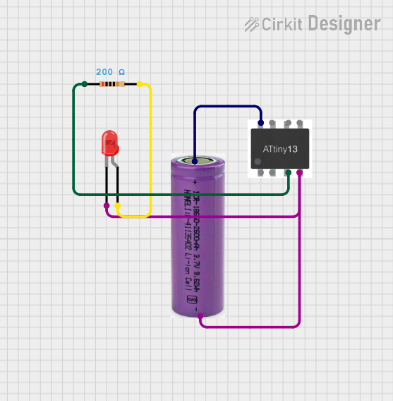


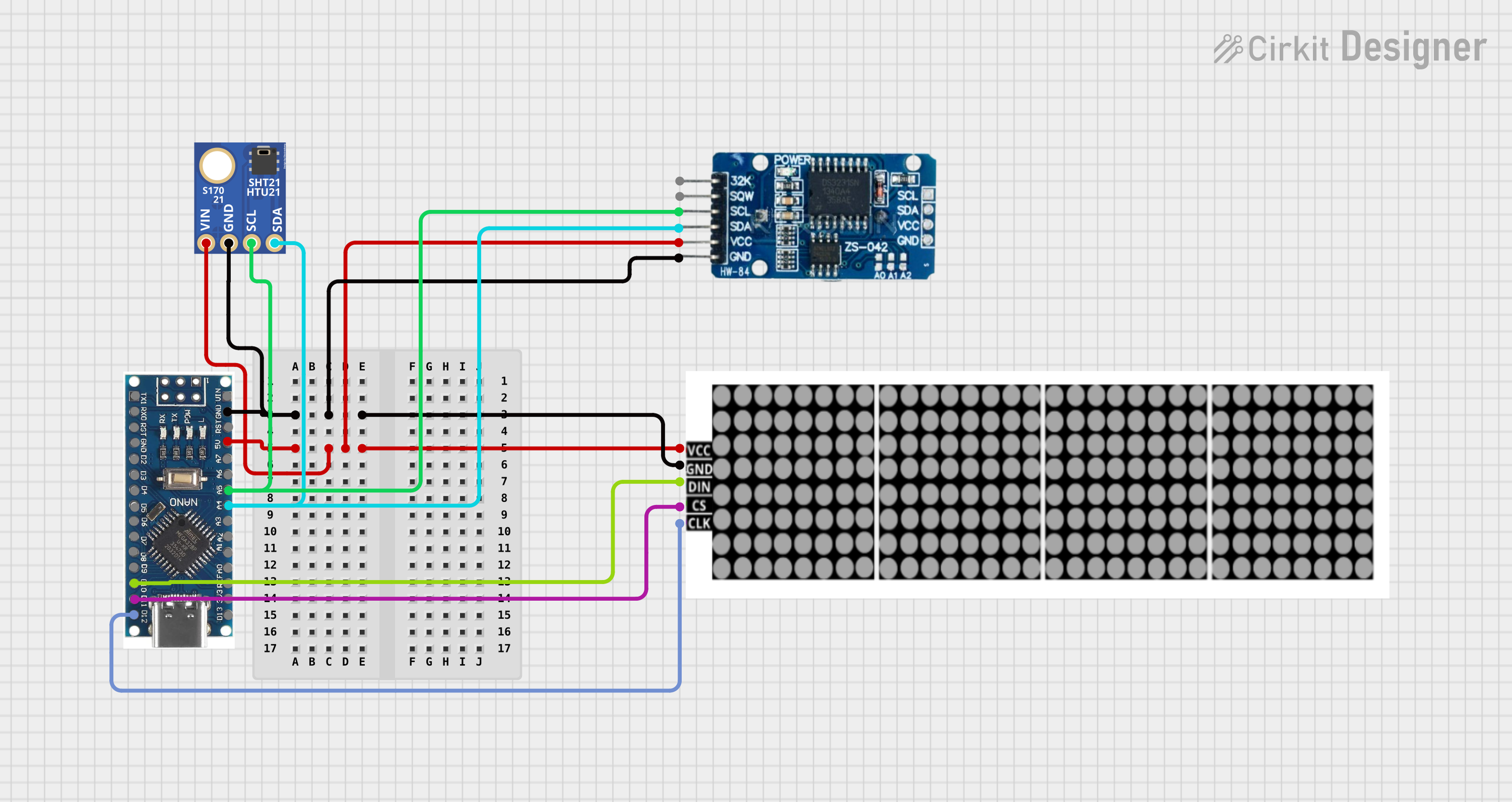
Explore Projects Built with ATtiny2313
Common Applications and Use Cases
- Home automation systems
- IoT devices and sensors
- Motor control and robotics
- LED control and lighting systems
- Data acquisition and processing
- Educational projects and prototyping
Technical Specifications
The ATtiny2313 is a robust microcontroller with the following key specifications:
| Parameter | Value |
|---|---|
| Architecture | 8-bit AVR |
| Flash Memory | 2KB |
| SRAM | 128 bytes |
| EEPROM | 128 bytes |
| Operating Voltage | 2.7V to 5.5V |
| Clock Speed | Up to 20 MHz |
| I/O Pins | 16 general-purpose I/O pins |
| Timers | 1 x 8-bit, 1 x 16-bit |
| Communication Interfaces | UART, SPI, I2C (TWI) |
| Package | 20-pin PDIP, SOIC, or QFN |
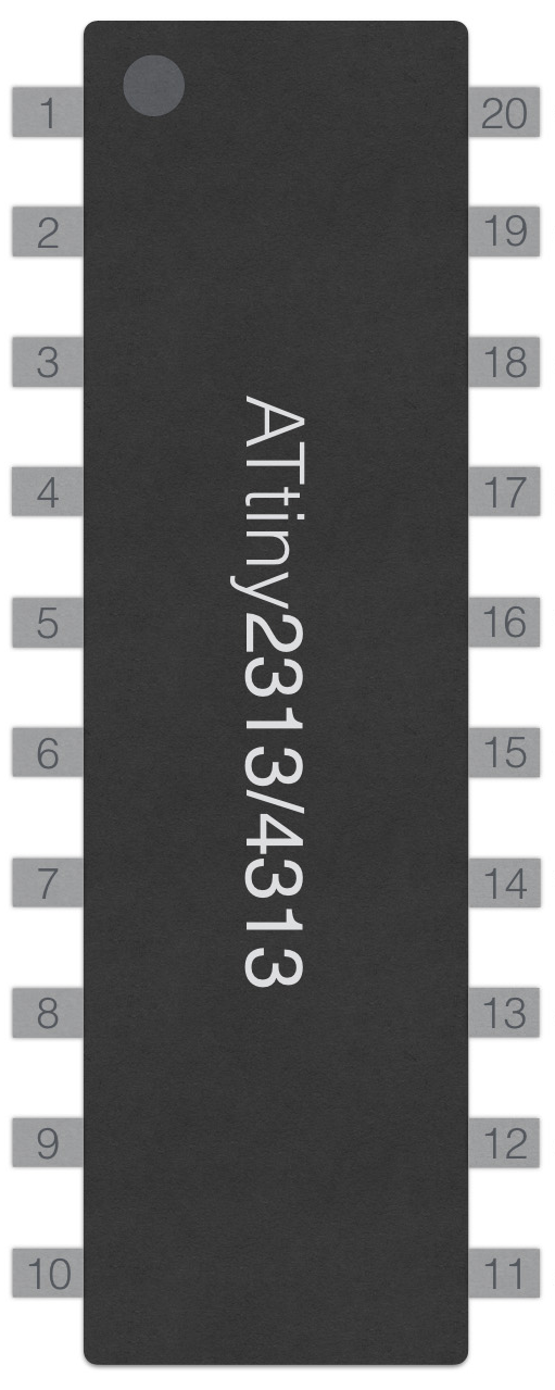
Pin Configuration and Descriptions
The ATtiny2313 has 20 pins, each with specific functions. Below is the pinout description:
| Pin Number | Pin Name | Description |
|---|---|---|
| 1 | RESET | Reset input (active low) |
| 2 | RXD | UART Receive |
| 3 | TXD | UART Transmit |
| 4 | XTAL1 | External clock/crystal input |
| 5 | XTAL2 | External clock/crystal output |
| 6 | PD2 | General-purpose I/O |
| 7 | PD3 | General-purpose I/O |
| 8 | PD4 | General-purpose I/O |
| 9 | VCC | Power supply (2.7V to 5.5V) |
| 10 | GND | Ground |
| 11 | PB0 | General-purpose I/O |
| 12 | PB1 | General-purpose I/O |
| 13 | PB2 | General-purpose I/O |
| 14 | PB3 | General-purpose I/O |
| 15 | PB4 | General-purpose I/O |
| 16 | PB5 | General-purpose I/O |
| 17 | PB6 | General-purpose I/O |
| 18 | PB7 | General-purpose I/O |
| 19 | AVCC | Analog power supply |
| 20 | AREF | Analog reference for ADC (if used) |
Usage Instructions
How to Use the ATtiny2313 in a Circuit
- Power Supply: Connect the VCC pin to a regulated power source (2.7V to 5.5V) and the GND pin to ground.
- Clock Source: Use the internal 8 MHz oscillator or connect an external crystal oscillator to XTAL1 and XTAL2.
- Programming: Use an AVR programmer (e.g., USBasp) to upload code via the ISP interface.
- I/O Configuration: Configure the I/O pins as input or output in the firmware using the DDRx registers.
- Communication: Utilize UART, SPI, or I2C for interfacing with other devices.
Important Considerations and Best Practices
- Decoupling Capacitors: Place a 0.1 µF capacitor between VCC and GND to reduce noise.
- Pull-up Resistors: Use pull-up resistors on the RESET pin to prevent accidental resets.
- Clock Selection: For precise timing, use an external crystal oscillator.
- Pin Protection: Avoid exceeding the voltage and current limits on I/O pins (max 40 mA per pin).
Example: Blinking an LED with ATtiny2313
Below is an example of how to blink an LED connected to pin PB0 using the ATtiny2313. This code can be written in AVR C and uploaded using an ISP programmer.
#include <avr/io.h>
#include <util/delay.h>

#define LED_PIN PB0  // Define the LED pin as PB0

int main(void) {
    DDRB |= (1 << LED_PIN);  // Set PB0 as an output pin

    while (1) {
        PORTB |= (1 << LED_PIN);  // Turn the LED on
        _delay_ms(500);          // Wait for 500 milliseconds
        PORTB &= ~(1 << LED_PIN); // Turn the LED off
        _delay_ms(500);          // Wait for 500 milliseconds
    }

    return 0;  // This line will never be reached
}
Using ATtiny2313 with Arduino UNO as a Programmer
The ATtiny2313 can be programmed using an Arduino UNO as an ISP (In-System Programmer). Follow these steps:
- Connect the Arduino UNO to the ATtiny2313:
- Arduino Pin 10 → ATtiny2313 RESET
- Arduino Pin 11 → ATtiny2313 MOSI (PB5)
- Arduino Pin 12 → ATtiny2313 MISO (PB6)
- Arduino Pin 13 → ATtiny2313 SCK (PB7)
- Arduino GND → ATtiny2313 GND
- Arduino 5V → ATtiny2313 VCC
- Load the "ArduinoISP" sketch onto the Arduino UNO.
- Use the Arduino IDE to upload your code to the ATtiny2313 by selecting "Upload Using Programmer."
Troubleshooting and FAQs
Common Issues
Microcontroller Not Responding:
- Ensure the power supply is stable and within the operating voltage range.
- Check the RESET pin for proper pull-up resistor configuration.
- Verify the connections between the programmer and the ATtiny2313.
Code Upload Fails:
- Confirm that the correct microcontroller is selected in the programming software.
- Ensure the ISP connections (MOSI, MISO, SCK, RESET) are secure.
- Check for conflicting devices on the SPI bus.
Unexpected Behavior in Circuit:
- Verify that the I/O pins are correctly configured in the code.
- Check for short circuits or incorrect wiring.
- Ensure decoupling capacitors are properly placed.
Tips for Troubleshooting
- Use a multimeter to check voltage levels and continuity.
- Test the circuit with a simple program (e.g., blinking an LED) to verify basic functionality.
- Double-check the fuse settings if using an external clock source.
By following this documentation, you can effectively utilize the ATtiny2313 in your projects and troubleshoot common issues with ease.