How to Use B-U585I-IOT02A: Examples, Pinouts, and Specs
Introduction
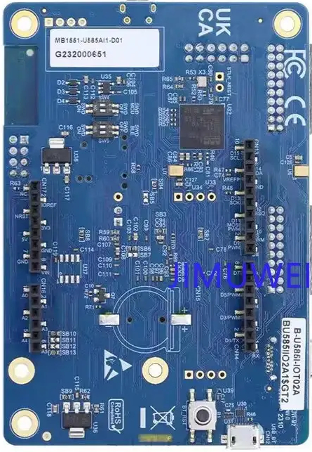
The B-U585I-IOT02A is a development board manufactured by STMicroelectronics, designed to accelerate the development of IoT (Internet of Things) applications. It is built around the STM32U585AI microcontroller, which features an Arm® Cortex®-M33 core with TrustZone® technology for enhanced security. The board integrates a variety of sensors, connectivity modules, and interfaces, making it an ideal platform for prototyping smart devices and IoT solutions.
Explore Projects Built with B-U585I-IOT02A


Explore Projects Built with B-U585I-IOT02A
Common Applications and Use Cases
- Smart home devices (e.g., connected thermostats, lighting systems)
- Industrial IoT (e.g., predictive maintenance, asset tracking)
- Wearable devices and health monitoring systems
- Environmental monitoring (e.g., air quality, temperature, humidity)
- Secure IoT applications requiring advanced cryptographic features
Technical Specifications
Key Technical Details
| Feature | Specification |
|---|---|
| Microcontroller | STM32U585AI (Arm® Cortex®-M33, 160 MHz, TrustZone® support) |
| Flash Memory | 2 MB internal Flash |
| RAM | 786 KB internal SRAM |
| Connectivity | Wi-Fi (ISM43362-M3G-L44), Bluetooth® Low Energy (v5.0), NFC |
| Sensors | Temperature, humidity, magnetometer, accelerometer, gyroscope, pressure |
| Power Supply | USB Type-C (5V) or external power supply |
| Interfaces | USB, UART, I2C, SPI, ADC, GPIO |
| Operating Voltage | 3.3V (I/O) |
| Dimensions | 95 mm x 50 mm |
| Development Environment | Compatible with STM32CubeIDE, Arduino IDE, and other IDEs |
Pin Configuration and Descriptions
The B-U585I-IOT02A board provides multiple headers and connectors for interfacing with external components. Below is a summary of the key pins and their functions:
GPIO Header Pinout
| Pin Number | Pin Name | Function | Voltage Level |
|---|---|---|---|
| 1 | 3V3 | 3.3V Power Output | 3.3V |
| 2 | GND | Ground | - |
| 3 | PA0 | GPIO / ADC Input | 3.3V |
| 4 | PA1 | GPIO / PWM Output | 3.3V |
| 5 | PB6 | I2C1_SCL (Clock Line) | 3.3V |
| 6 | PB7 | I2C1_SDA (Data Line) | 3.3V |
| 7 | PC10 | UART4_TX (Transmit) | 3.3V |
| 8 | PC11 | UART4_RX (Receive) | 3.3V |
Sensor Connections
| Sensor | Interface | Pin Names | Description |
|---|---|---|---|
| Temperature | I2C | PB6 (SCL), PB7 (SDA) | Measures ambient temperature |
| Humidity | I2C | PB6 (SCL), PB7 (SDA) | Measures relative humidity |
| Magnetometer | I2C | PB6 (SCL), PB7 (SDA) | Detects magnetic fields |
| Accelerometer | I2C | PB6 (SCL), PB7 (SDA) | Measures acceleration in 3 axes |
| Gyroscope | I2C | PB6 (SCL), PB7 (SDA) | Measures angular velocity |
| Pressure | I2C | PB6 (SCL), PB7 (SDA) | Measures atmospheric pressure |
Usage Instructions
How to Use the Component in a Circuit
Powering the Board:
- Connect the board to a USB Type-C cable for power and programming.
- Alternatively, use an external 5V power supply via the dedicated pins.
Programming the Board:
- Install STM32CubeIDE or Arduino IDE on your computer.
- Connect the board to your computer via USB.
- Select the appropriate board and port in your IDE.
- Write and upload your code to the board.
Interfacing with Sensors:
- Use the I2C interface to communicate with onboard sensors.
- Ensure proper initialization of the I2C bus in your code.
Using Connectivity Features:
- Configure the Wi-Fi or Bluetooth® module using the provided libraries.
- For NFC, use the onboard NFC antenna and relevant libraries for data exchange.
Important Considerations and Best Practices
- Power Supply: Ensure a stable 5V power source to avoid damage to the board.
- Pin Voltage Levels: Do not exceed 3.3V on GPIO pins to prevent damage.
- Firmware Updates: Regularly update the firmware using STM32CubeProgrammer for optimal performance.
- Debugging: Use the onboard ST-LINK/V2-1 debugger for troubleshooting and debugging your code.
Example Code for Arduino IDE
Below is an example of how to read temperature and humidity data from the onboard sensor using the Arduino IDE:
#include <Wire.h>
#include <HTS221Sensor.h> // Include the library for the HTS221 sensor

// Define I2C address for the HTS221 sensor
#define HTS221_I2C_ADDRESS 0x5F

// Create an instance of the HTS221 sensor
HTS221Sensor hts221(&Wire);

void setup() {
  Serial.begin(9600); // Initialize serial communication
  Wire.begin();       // Initialize I2C communication

  // Initialize the HTS221 sensor
  if (hts221.begin(HTS221_I2C_ADDRESS)) {
    Serial.println("HTS221 sensor initialized successfully.");
  } else {
    Serial.println("Failed to initialize HTS221 sensor.");
    while (1); // Halt execution if initialization fails
  }
}

void loop() {
  float temperature, humidity;

  // Read temperature and humidity from the sensor
  if (hts221.readTemperature(&temperature) && hts221.readHumidity(&humidity)) {
    Serial.print("Temperature: ");
    Serial.print(temperature);
    Serial.println(" °C");

    Serial.print("Humidity: ");
    Serial.print(humidity);
    Serial.println(" %");
  } else {
    Serial.println("Failed to read data from HTS221 sensor.");
  }

  delay(1000); // Wait for 1 second before the next reading
}
Troubleshooting and FAQs
Common Issues Users Might Face
Board Not Detected by IDE:
- Ensure the USB cable is properly connected and functional.
- Verify that the correct board and port are selected in the IDE.
- Update the USB drivers if necessary.
Sensor Data Not Reading:
- Check the I2C connections and ensure the correct I2C address is used.
- Verify that the sensor initialization code is correct.
Wi-Fi or Bluetooth® Not Working:
- Ensure the correct libraries are included and initialized in your code.
- Check the antenna connections and signal strength.
Power Issues:
- Verify that the board is receiving a stable 5V supply.
- Avoid powering high-current peripherals directly from the board.
Solutions and Tips for Troubleshooting
- Use the onboard LEDs to check the board's status (e.g., power, activity).
- Refer to the STM32CubeIDE or Arduino IDE debug console for error messages.
- Consult the B-U585I-IOT02A user manual and datasheet for detailed technical information.
- If issues persist, contact STMicroelectronics support or consult the community forums.