How to Use Buck Converter: Examples, Pinouts, and Specs
Introduction
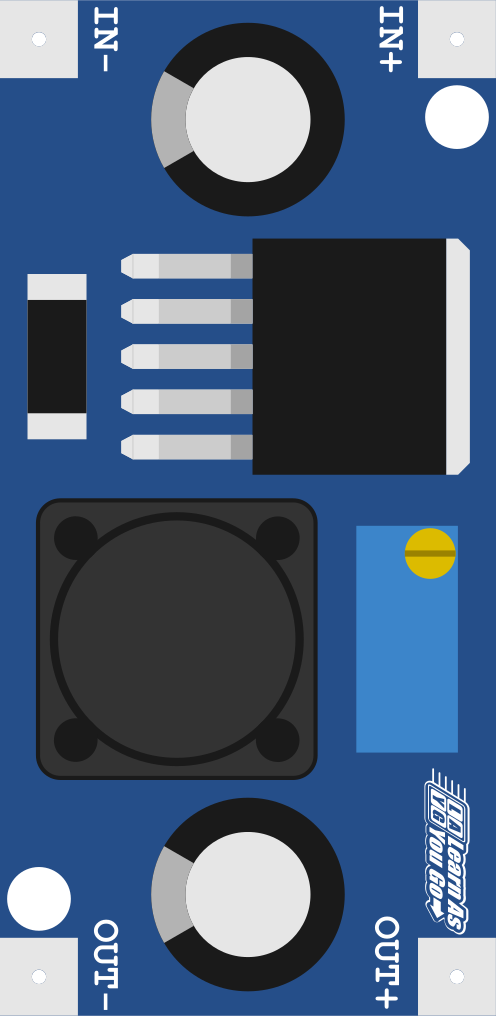
A buck converter is a DC-DC power converter designed to step down voltage while stepping up current. It achieves this by using a combination of a switching element (such as a transistor), a diode, an inductor, and a capacitor. Buck converters are highly efficient and are widely used in applications where power efficiency and precise voltage regulation are critical.
Explore Projects Built with Buck Converter


Explore Projects Built with Buck Converter
Common Applications and Use Cases
- Powering low-voltage devices (e.g., microcontrollers, sensors) from higher-voltage sources
- Battery-powered systems to regulate voltage levels
- Voltage regulation in renewable energy systems (e.g., solar panels)
- Power supplies for consumer electronics, such as laptops and smartphones
- Automotive electronics for stepping down voltage from a car battery
Technical Specifications
Below are the general technical specifications for a typical buck converter. Note that actual values may vary depending on the specific model or design.
Key Technical Details
- Input Voltage Range: 4.5V to 40V (varies by model)
- Output Voltage Range: 0.8V to 36V (adjustable or fixed)
- Output Current: Up to 10A (depending on the design)
- Efficiency: Up to 95% (depending on load and input/output conditions)
- Switching Frequency: 100 kHz to 1 MHz
- Operating Temperature: -40°C to +125°C
Pin Configuration and Descriptions
The pinout of a buck converter module may vary depending on the specific design. Below is an example of a common pin configuration for a basic buck converter module:
| Pin Name | Description |
|---|---|
| VIN | Input voltage pin. Connect the higher input voltage source to this pin. |
| GND | Ground pin. Connect to the ground of the input and output circuits. |
| VOUT | Output voltage pin. Provides the stepped-down voltage to the load. |
| EN (Enable) | Enable pin. Used to turn the converter on or off. High = ON, Low = OFF. |
| FB (Feedback) | Feedback pin. Used to set or monitor the output voltage (via a resistor divider). |
Usage Instructions
How to Use the Buck Converter in a Circuit
- Connect the Input Voltage:
- Connect the positive terminal of the input voltage source to the
VINpin. - Connect the negative terminal of the input voltage source to the
GNDpin.
- Connect the positive terminal of the input voltage source to the
- Set the Output Voltage (if adjustable):
- Use the onboard potentiometer (if available) or an external resistor divider connected to the
FBpin to set the desired output voltage. - Refer to the datasheet or module documentation for the formula to calculate the resistor values.
- Use the onboard potentiometer (if available) or an external resistor divider connected to the
- Connect the Load:
- Connect the positive terminal of the load to the
VOUTpin. - Connect the negative terminal of the load to the
GNDpin.
- Connect the positive terminal of the load to the
- Enable the Converter:
- If the module has an
ENpin, ensure it is pulled high to enable the converter. If unused, connect it toVINor a logic high voltage.
- If the module has an
Important Considerations and Best Practices
- Input Voltage: Ensure the input voltage is within the specified range of the buck converter module.
- Output Current: Do not exceed the maximum output current rating to avoid overheating or damage.
- Heat Dissipation: For high-power applications, consider adding a heatsink or active cooling to the module.
- Inductor Selection: If designing your own buck converter, choose an inductor with appropriate current ratings and low DC resistance.
- Capacitor Selection: Use low-ESR capacitors for better performance and stability.
- Ripple and Noise: Add additional filtering capacitors if the output voltage ripple is too high for your application.
Example: Using a Buck Converter with Arduino UNO
Below is an example of how to use a buck converter to power an Arduino UNO from a 12V source:
- Connect the 12V input to the
VINandGNDpins of the buck converter. - Adjust the output voltage to 5V using the onboard potentiometer.
- Connect the
VOUTpin of the buck converter to the5Vpin of the Arduino UNO. - Connect the
GNDpin of the buck converter to theGNDpin of the Arduino UNO.
// Example Arduino code to blink an LED powered by a buck converter

const int ledPin = 13; // Pin connected to the onboard LED

void setup() {
  pinMode(ledPin, OUTPUT); // Set the LED pin as an output
}

void loop() {
  digitalWrite(ledPin, HIGH); // Turn the LED on
  delay(1000);                // Wait for 1 second
  digitalWrite(ledPin, LOW);  // Turn the LED off
  delay(1000);                // Wait for 1 second
}
Troubleshooting and FAQs
Common Issues and Solutions
No Output Voltage:
- Check if the
ENpin is properly connected or pulled high. - Verify that the input voltage is within the specified range.
- Inspect the connections for loose wires or poor solder joints.
- Check if the
Output Voltage is Incorrect:
- If the output is adjustable, ensure the potentiometer or resistor divider is set correctly.
- Check for excessive load current that may cause voltage drops.
Overheating:
- Ensure the load current does not exceed the maximum rating.
- Add a heatsink or improve ventilation around the module.
High Output Ripple:
- Add additional filtering capacitors to the output.
- Ensure the inductor and capacitors are properly rated for the application.
Module Not Powering On:
- Verify the polarity of the input voltage connections.
- Check for a blown fuse or damaged components.
FAQs
Q: Can I use a buck converter to power sensitive electronics?
A: Yes, but ensure the output voltage ripple is low. You may need to add additional filtering capacitors for sensitive devices.
Q: What happens if I exceed the input voltage range?
A: Exceeding the input voltage range can damage the buck converter. Always use a voltage source within the specified range.
Q: Can I use a buck converter to step up voltage?
A: No, a buck converter is designed only to step down voltage. For stepping up voltage, use a boost converter.
Q: How do I calculate the output voltage for an adjustable buck converter?
A: Refer to the datasheet for the specific formula, which typically involves the resistor values in the feedback network.
By following this documentation, you can effectively use a buck converter in your projects while ensuring optimal performance and reliability.