Cirkit Designer Logo
Cirkit Designer
Your all-in-one circuit design IDE
Home / 
Component Documentation

How to Use r307: Examples, Pinouts, and Specs
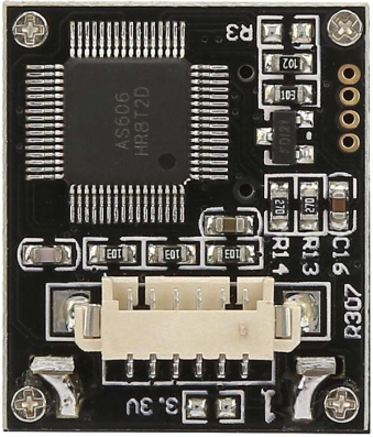
Image of r307
Cirkit Designer LogoDesign with r307 in Cirkit Designer

Introduction

The R307 is a resistor, an essential passive electronic component used to control the flow of electric current in a circuit. Resistors are widely used in various applications, from simple circuits to complex electronic devices, to limit current, divide voltages, and provide biasing for active elements.

Explore Projects Built with r307
Use Cirkit Designer to design, explore, and prototype these projects online. Some projects support real-time simulation. Click "Open Project" to start designing instantly!
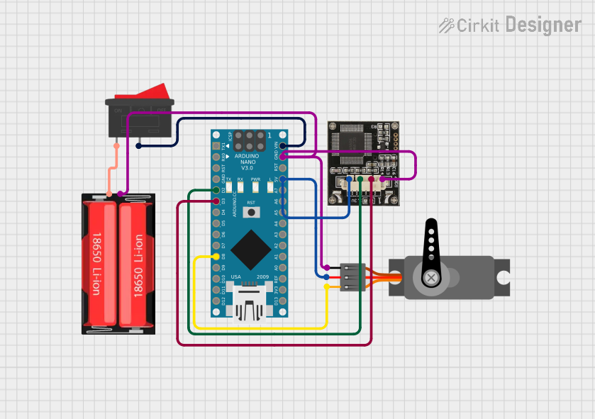
Arduino Nano Controlled Fingerprint-Authenticated Servo Lock
Image of Fingerprint_Door_Lock: A project utilizing r307 in a practical application
This circuit features an Arduino Nano microcontroller interfaced with an r307 fingerprint sensor and a servo motor. The Arduino communicates with the r307 sensor via digital pins D2 and D3 for RX/TX serial communication and controls the servo motor through the PWM signal on pin D8. Power is managed through a rocker switch connected to an 18650 Li-Ion battery, which supplies power to the Arduino's VIN pin and, through the Arduino, to the servo and sensor.
Cirkit Designer LogoOpen Project in Cirkit Designer
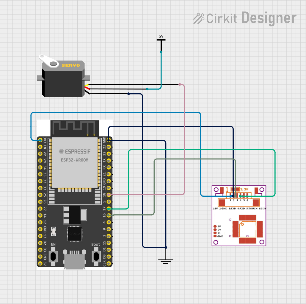
ESP32-Based Wi-Fi Controlled Fingerprint Access System with Servo Lock
Image of Automatic Car Door Opening System: A project utilizing r307 in a practical application
This circuit features an ESP32 microcontroller interfaced with an R307 fingerprint sensor and a servo motor. The ESP32 reads fingerprint data from the sensor and controls the servo motor based on the input. Power is supplied to the components via Vcc and GND connections.
Cirkit Designer LogoOpen Project in Cirkit Designer
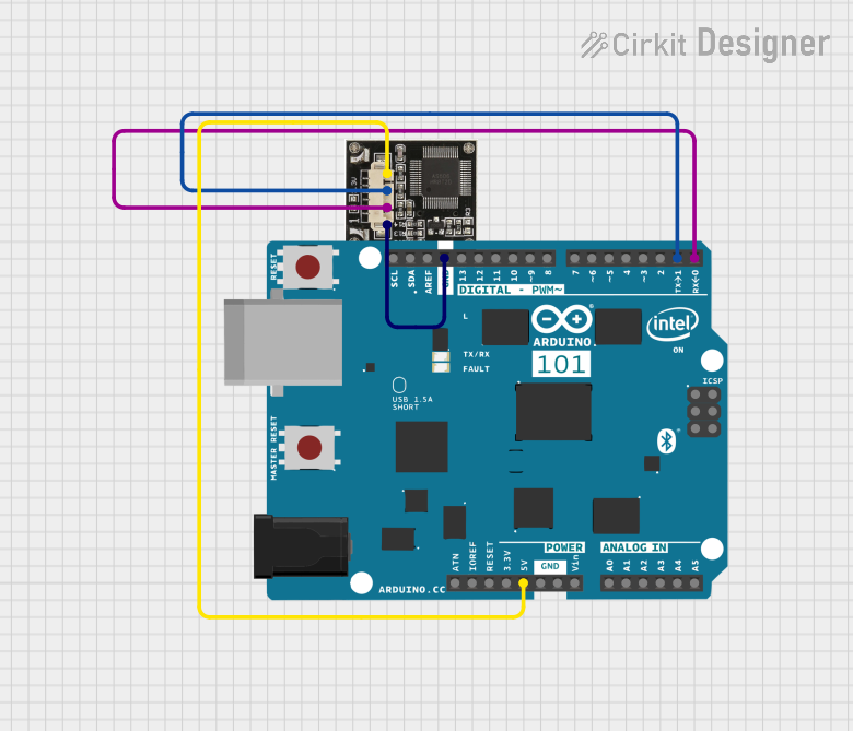
Arduino 101 Fingerprint Identification System
Image of THUMBRECOGNITION: A project utilizing r307 in a practical application
This circuit connects an R307 fingerprint sensor to an Arduino 101 microcontroller for biometric identification. The sensor's VCC and GND are connected to the Arduino's 5V and GND for power, while the sensor's TX and RX pins are connected to the Arduino's RX (D0) and TX (D1) pins for serial communication. The provided Arduino code is configured to initialize the sensor, capture fingerprints, and search for matches in its database.
Cirkit Designer LogoOpen Project in Cirkit Designer
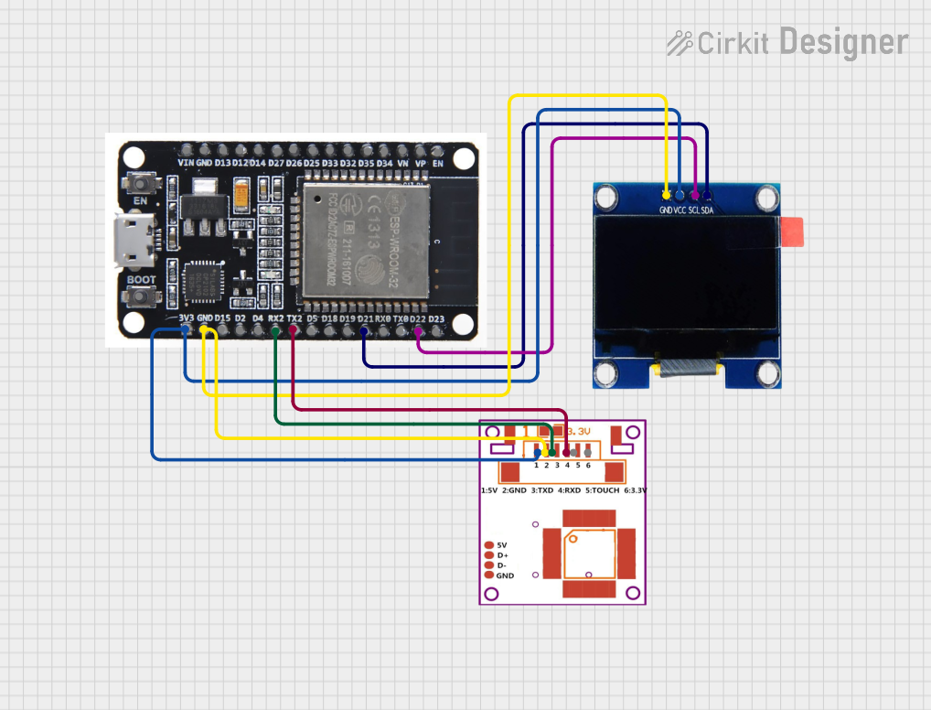
ESP32-Based Fingerprint Authentication System with OLED Display
Image of Attendance system using fingerprint: A project utilizing r307 in a practical application
This circuit features an ESP32 microcontroller connected to an R307 Fingerprint Sensor and an OLED 1.3" display. The ESP32 powers both the sensor and the display, communicates with the fingerprint sensor via serial connection (RX2/TX2), and interfaces with the OLED display using I2C protocol (D21 for SDA, D22 for SCL). The circuit is likely designed for biometric authentication with visual feedback on the OLED screen.
Cirkit Designer LogoOpen Project in Cirkit Designer

Explore Projects Built with r307

Use Cirkit Designer to design, explore, and prototype these projects online. Some projects support real-time simulation. Click "Open Project" to start designing instantly!
Image of Fingerprint_Door_Lock: A project utilizing r307 in a practical application
Arduino Nano Controlled Fingerprint-Authenticated Servo Lock
This circuit features an Arduino Nano microcontroller interfaced with an r307 fingerprint sensor and a servo motor. The Arduino communicates with the r307 sensor via digital pins D2 and D3 for RX/TX serial communication and controls the servo motor through the PWM signal on pin D8. Power is managed through a rocker switch connected to an 18650 Li-Ion battery, which supplies power to the Arduino's VIN pin and, through the Arduino, to the servo and sensor.
Cirkit Designer LogoOpen Project in Cirkit Designer
Image of Automatic Car Door Opening System: A project utilizing r307 in a practical application
ESP32-Based Wi-Fi Controlled Fingerprint Access System with Servo Lock
This circuit features an ESP32 microcontroller interfaced with an R307 fingerprint sensor and a servo motor. The ESP32 reads fingerprint data from the sensor and controls the servo motor based on the input. Power is supplied to the components via Vcc and GND connections.
Cirkit Designer LogoOpen Project in Cirkit Designer
Image of THUMBRECOGNITION: A project utilizing r307 in a practical application
Arduino 101 Fingerprint Identification System
This circuit connects an R307 fingerprint sensor to an Arduino 101 microcontroller for biometric identification. The sensor's VCC and GND are connected to the Arduino's 5V and GND for power, while the sensor's TX and RX pins are connected to the Arduino's RX (D0) and TX (D1) pins for serial communication. The provided Arduino code is configured to initialize the sensor, capture fingerprints, and search for matches in its database.
Cirkit Designer LogoOpen Project in Cirkit Designer
Image of Attendance system using fingerprint: A project utilizing r307 in a practical application
ESP32-Based Fingerprint Authentication System with OLED Display
This circuit features an ESP32 microcontroller connected to an R307 Fingerprint Sensor and an OLED 1.3" display. The ESP32 powers both the sensor and the display, communicates with the fingerprint sensor via serial connection (RX2/TX2), and interfaces with the OLED display using I2C protocol (D21 for SDA, D22 for SCL). The circuit is likely designed for biometric authentication with visual feedback on the OLED screen.
Cirkit Designer LogoOpen Project in Cirkit Designer

Technical Specifications

Key Technical Details

  • Resistance Value: The R307's resistance value will be specified in ohms (Ω). The actual value should be indicated by the color bands on the resistor or in the product datasheet.
  • Tolerance: This indicates how much the actual resistance can vary from the stated value, typically given in percentage (e.g., ±1%, ±5%).
  • Power Rating: The maximum power the resistor can dissipate without damage, usually given in watts (W).
  • Temperature Coefficient: This specifies how the resistance value changes with temperature, given in parts per million per degree Celsius (ppm/°C).

Pin Configuration and Descriptions

Since a resistor is a two-terminal component, it does not have a complex pin configuration. The two terminals are identical and interchangeable:

Pin Description
1 Terminal A
2 Terminal B

Usage Instructions

How to Use the R307 in a Circuit

  1. Identify the Resistance Value: Use the color code or datasheet to determine the resistance value of the R307.
  2. Determine the Orientation: There is no polarity for resistors; they can be connected in any direction.
  3. Calculate the Required Power Rating: Ensure the power rating meets or exceeds the power that will be dissipated by the resistor in your specific application.
  4. Soldering: When soldering the R307 into a circuit, avoid excessive heat, which could damage the resistor or alter its value.

Important Considerations and Best Practices

  • Tolerance Matching: For precision circuits, select resistors with a tight tolerance.
  • Power Rating: Always choose a resistor with a power rating that can handle the expected power dissipation.
  • Temperature Effects: Be aware of the temperature coefficient if the resistor will be used in environments with large temperature variations.
  • Series and Parallel Connections: Use series connections to increase total resistance and parallel connections to decrease it.

Troubleshooting and FAQs

Common Issues

  • Excessive Heat: If the resistor is too hot, it may be dissipating more power than its rating allows. Check the circuit design and power calculations.
  • Unexpected Resistance Value: Ensure the resistor is not damaged and that the correct resistance value was selected for the application.

Solutions and Tips for Troubleshooting

  • Check the Circuit Design: Verify that the resistor value and power rating are appropriate for the circuit.
  • Inspect for Physical Damage: Look for signs of burning or damage that could affect the resistor's performance.
  • Measure Resistance: Use a multimeter to measure the actual resistance of the R307.

FAQs

Q: Can I replace the R307 with a resistor of a different value? A: It depends on the circuit requirements. The replacement should have the same or higher power rating and a resistance value that meets the circuit's needs.

Q: Does the R307 have a polarity? A: No, resistors are non-polarized components and can be connected in any direction.

Q: What happens if I exceed the power rating of the R307? A: Exceeding the power rating can cause the resistor to overheat, potentially leading to failure or damage to the circuit.

Q: How do I know if the R307 is faulty? A: A faulty resistor may show signs of physical damage or measure an incorrect resistance value with a multimeter.


Note: The R307 is a generic designation for a resistor and may not correspond to a specific product model. Always refer to the manufacturer's datasheet for exact specifications and ensure that the component meets the requirements of your application.