How to Use L89HA Breakout: Examples, Pinouts, and Specs
Introduction
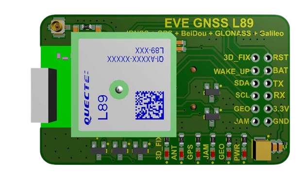
The L89HA Breakout Board is a versatile and user-friendly platform designed to facilitate the use of the L89HA microcontroller. This breakout board simplifies the process of connecting to and programming the L89HA, making it an ideal choice for hobbyists, educators, and professionals. Common applications include prototyping, educational projects, and small-scale automation systems.
Explore Projects Built with L89HA Breakout

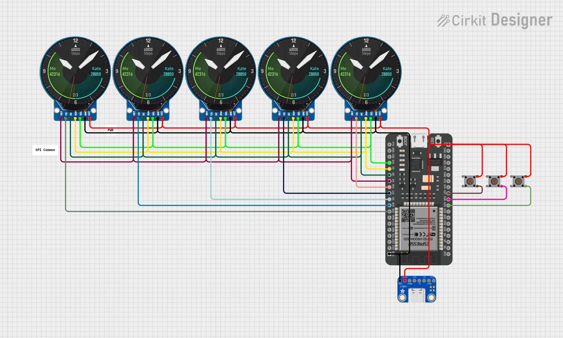
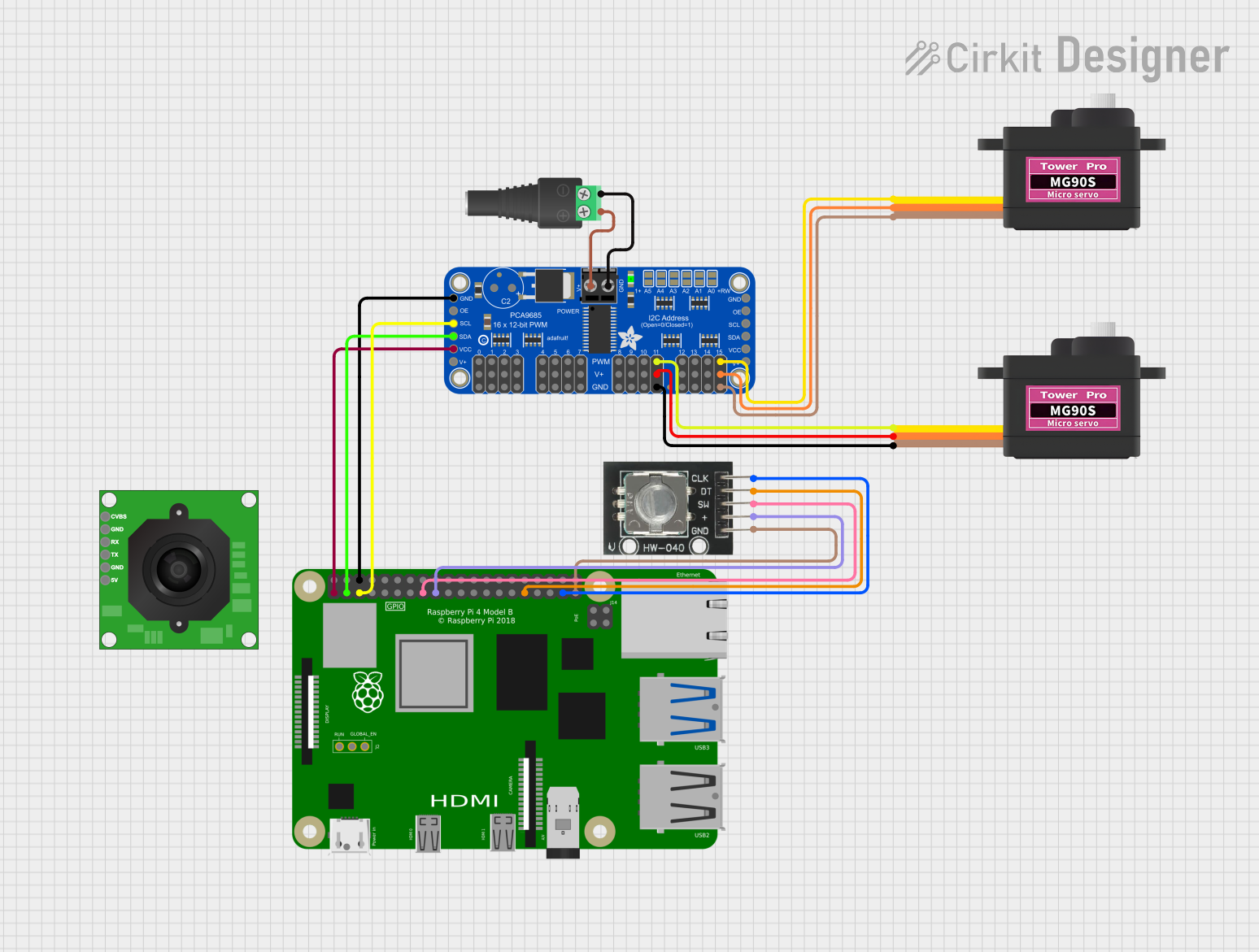
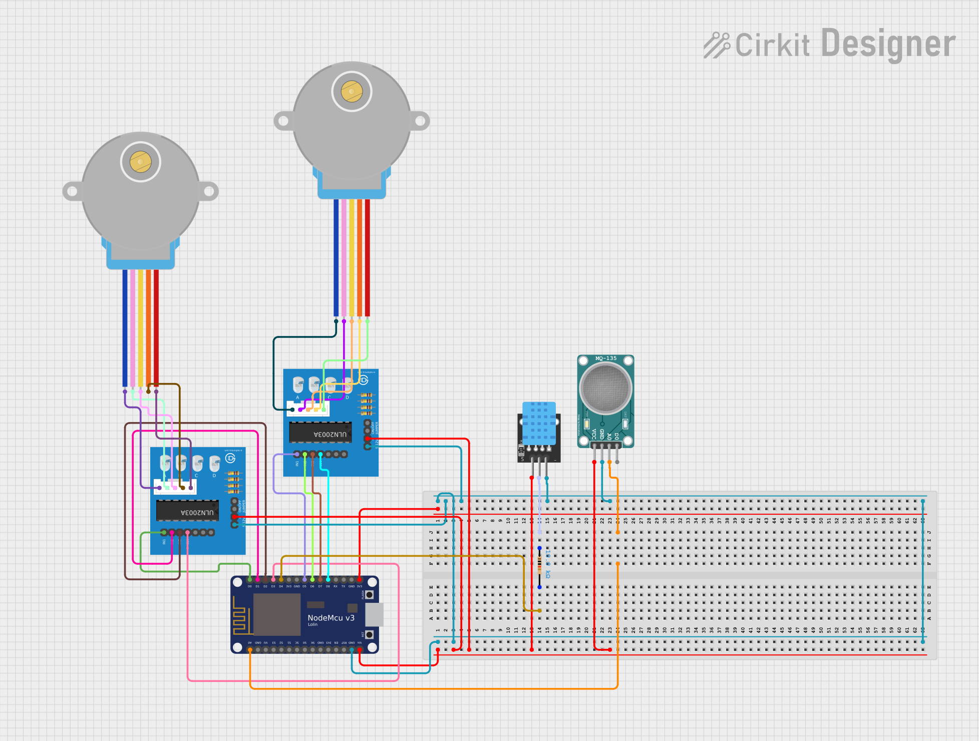
Explore Projects Built with L89HA Breakout
Technical Specifications
Key Technical Details
- Microcontroller: L89HA
- Operating Voltage: 3.3V - 5V
- Digital I/O Pins: 14 (of which 6 provide PWM output)
- Analog Input Pins: 6
- DC Current per I/O Pin: 40 mA
- Flash Memory: 32 KB (of which 2 KB used by bootloader)
- SRAM: 2 KB
- EEPROM: 1 KB
- Clock Speed: 16 MHz
Pin Configuration and Descriptions
| Pin Number | Function | Description |
|---|---|---|
| 1 | VCC | Power supply (3.3V - 5V) |
| 2 | GND | Ground |
| 3-8 | Digital I/O | Digital input/output pins |
| 9-14 | PWM/Digital I/O | PWM capable digital input/output pins |
| A0-A5 | Analog Input | Analog input pins |
| RST | Reset | Resets the microcontroller |
| TX | Transmit | UART transmit |
| RX | Receive | UART receive |
| SCL | I2C Clock | I2C clock line |
| SDA | I2C Data | I2C data line |
Usage Instructions
Connecting the L89HA Breakout Board
- Powering the Board: Connect the VCC pin to a 3.3V or 5V power supply, and the GND pin to the ground.
- Programming: Use the TX and RX pins to upload code from your computer to the L89HA microcontroller.
- Digital I/O: Connect digital sensors or actuators to the digital I/O pins as required by your project.
- Analog Input: Connect analog sensors to the A0-A5 pins for analog input.
- PWM Output: Use PWM-capable pins for controlling devices like servo motors or LEDs with variable intensity.
Best Practices
- Always disconnect the board from the power source before making or altering connections.
- Use a current limiting resistor with LEDs to prevent damage.
- Avoid exposing the board to static electricity or moisture.
- Ensure that the power supply does not exceed the recommended voltage.
Example Code for Arduino UNO
// Example code for blinking an LED connected to pin 3 of the L89HA Breakout Board

void setup() {
  pinMode(3, OUTPUT); // Set pin 3 as an output
}

void loop() {
  digitalWrite(3, HIGH); // Turn the LED on
  delay(1000);           // Wait for a second
  digitalWrite(3, LOW);  // Turn the LED off
  delay(1000);           // Wait for a second
}
Troubleshooting and FAQs
Common Issues
- Board not powering on: Ensure that the VCC and GND connections are correct and the power supply is within the specified range.
- Unable to upload code: Check the TX and RX connections, and ensure the correct board and port are selected in your IDE.
- Inconsistent behavior: Verify that all connections are secure and there are no shorts on the board.
FAQs
Q: Can I use the L89HA Breakout Board with a 5V power supply? A: Yes, the board can be powered with a 3.3V to 5V power supply.
Q: How do I reset the microcontroller? A: Briefly connect the RST pin to GND to reset the microcontroller.
Q: What should I do if a pin stops working? A: Check for any physical damage to the pin or board. If there's no visible damage, try using another pin and check your code for errors.
For further assistance, please contact 7Semi support or refer to the community forums for help from other users.