
How to Use AS608: Examples, Pinouts, and Specs
 Design with AS608 in Cirkit Designer
Introduction
The AS608 is a fingerprint sensor module manufactured by Synochip, with the part ID JM-101. This module is designed to provide reliable biometric authentication capabilities. It features a compact design, high accuracy, and fast response time, making it ideal for applications such as security systems, access control, time attendance systems, and embedded devices requiring fingerprint recognition.
The AS608 integrates an optical fingerprint sensor, image processing algorithms, and a communication interface, enabling seamless integration into various electronic systems. Its robust performance and ease of use make it a popular choice for developers and engineers.
Explore Projects Built with AS608
 Open Project in Cirkit Designer
 Open Project in Cirkit Designer
 Open Project in Cirkit Designer
 Open Project in Cirkit Designer
Explore Projects Built with AS608
Open Project in Cirkit DesignerOpen Project in Cirkit DesignerOpen Project in Cirkit DesignerOpen Project in Cirkit DesignerTechnical Specifications
Below are the key technical details of the AS608 fingerprint sensor module:
| Parameter | Specification |
|---|---|
| Manufacturer | Synochip |
| Part ID | JM-101 |
| Supply Voltage | 3.6V to 6.0V |
| Operating Current | < 120mA |
| Peak Current | < 150mA |
| Fingerprint Capacity | 162 templates |
| Image Resolution | 508 DPI |
| Communication Interface | UART (TTL) |
| Baud Rate | Configurable (Default: 57600 bps) |
| Working Temperature | -20°C to +50°C |
| Storage Temperature | -40°C to +85°C |
| Module Dimensions | 20mm x 20mm x 10mm |
Pin Configuration and Descriptions
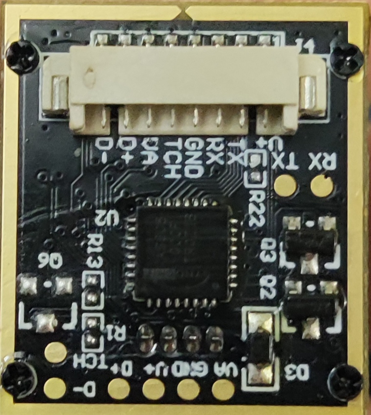
The AS608 module has a 6-pin interface for power and communication. The pinout is as follows:
| Pin | Name | Description |
|---|---|---|
| 1 | VCC | Power supply input (3.6V to 6.0V) |
| 2 | GND | Ground |
| 3 | TX | UART Transmit (Data output from the module) |
| 4 | RX | UART Receive (Data input to the module) |
| 5 | TOUCH | Touch detection signal (active high) |
| 6 | NC | Not connected (reserved for future use) |
Usage Instructions
How to Use the AS608 in a Circuit
- Power Supply: Connect the VCC pin to a regulated 3.6V to 6.0V power source and the GND pin to the ground of your circuit.
- UART Communication: Connect the TX and RX pins to the corresponding UART pins of your microcontroller or development board (e.g., Arduino UNO). Ensure the baud rate is set to match the module's default or configured value (57600 bps by default).
- Touch Signal: Optionally, use the TOUCH pin to detect when a finger is placed on the sensor. This pin outputs a high signal when a touch is detected.
Important Considerations and Best Practices
- Power Stability: Ensure a stable power supply to avoid communication errors or unreliable performance.
- Baud Rate Configuration: If you need to change the baud rate, refer to the module's datasheet for the appropriate commands.
- Fingerprint Enrollment: Use the module's built-in commands to enroll fingerprints. Each fingerprint is stored as a template in the module's internal memory.
- Environmental Conditions: Avoid exposing the module to extreme temperatures or high humidity, as this may affect its performance.
Example: Connecting AS608 to Arduino UNO
Below is an example of how to use the AS608 with an Arduino UNO for fingerprint enrollment and verification:
Circuit Connections
- Connect the AS608's
VCCto the Arduino's5Vpin. - Connect the AS608's
GNDto the Arduino'sGNDpin. - Connect the AS608's
TXto the Arduino'sD2pin (via a voltage divider if needed). - Connect the AS608's
RXto the Arduino'sD3pin.
Arduino Code Example
#include <Adafruit_Fingerprint.h>
#include <SoftwareSerial.h>

// Define the software serial pins for communication with AS608
SoftwareSerial mySerial(2, 3); // RX, TX

// Initialize the fingerprint sensor
Adafruit_Fingerprint finger(&mySerial);

void setup() {
  Serial.begin(9600); // Initialize serial monitor
  mySerial.begin(57600); // Initialize AS608 communication

  // Initialize the fingerprint sensor
  if (finger.begin()) {
    Serial.println("Fingerprint sensor initialized successfully!");
  } else {
    Serial.println("Failed to initialize fingerprint sensor. Check connections.");
    while (1); // Halt execution if initialization fails
  }
}

void loop() {
  Serial.println("Place your finger on the sensor...");
  int result = finger.getImage(); // Capture fingerprint image

  if (result == FINGERPRINT_OK) {
    Serial.println("Fingerprint image captured successfully!");
    // Additional processing can be added here
  } else if (result == FINGERPRINT_NOFINGER) {
    Serial.println("No finger detected. Please try again.");
  } else {
    Serial.println("Error capturing fingerprint image.");
  }

  delay(1000); // Wait before the next attempt
}
Troubleshooting and FAQs
Common Issues and Solutions
Issue: The fingerprint sensor does not respond.
- Solution: Check the power supply and ensure the VCC and GND pins are properly connected. Verify the UART connections and baud rate settings.
Issue: Fingerprint enrollment fails.
- Solution: Ensure the finger is placed correctly on the sensor. Clean the sensor surface to remove dirt or smudges.
Issue: Communication errors between the sensor and microcontroller.
- Solution: Verify the TX and RX connections. Ensure the baud rate of the microcontroller matches the sensor's baud rate.
Issue: The sensor does not detect a finger.
- Solution: Check the TOUCH pin signal. If the pin does not go high when a finger is placed, the sensor may be faulty.
FAQs
Q: Can the AS608 store multiple fingerprints?
- A: Yes, the AS608 can store up to 162 fingerprint templates in its internal memory.
Q: Is the AS608 compatible with 3.3V microcontrollers?
- A: Yes, but you may need a level shifter for the UART communication lines if the microcontroller operates at 3.3V.
Q: How do I change the baud rate of the AS608?
- A: Use the appropriate command from the module's datasheet to configure the baud rate.
Q: Can the AS608 be used outdoors?
- A: The AS608 is not designed for outdoor use. Protect it from direct sunlight, rain, and extreme temperatures for optimal performance.