How to Use NEO 6M: Examples, Pinouts, and Specs
Introduction
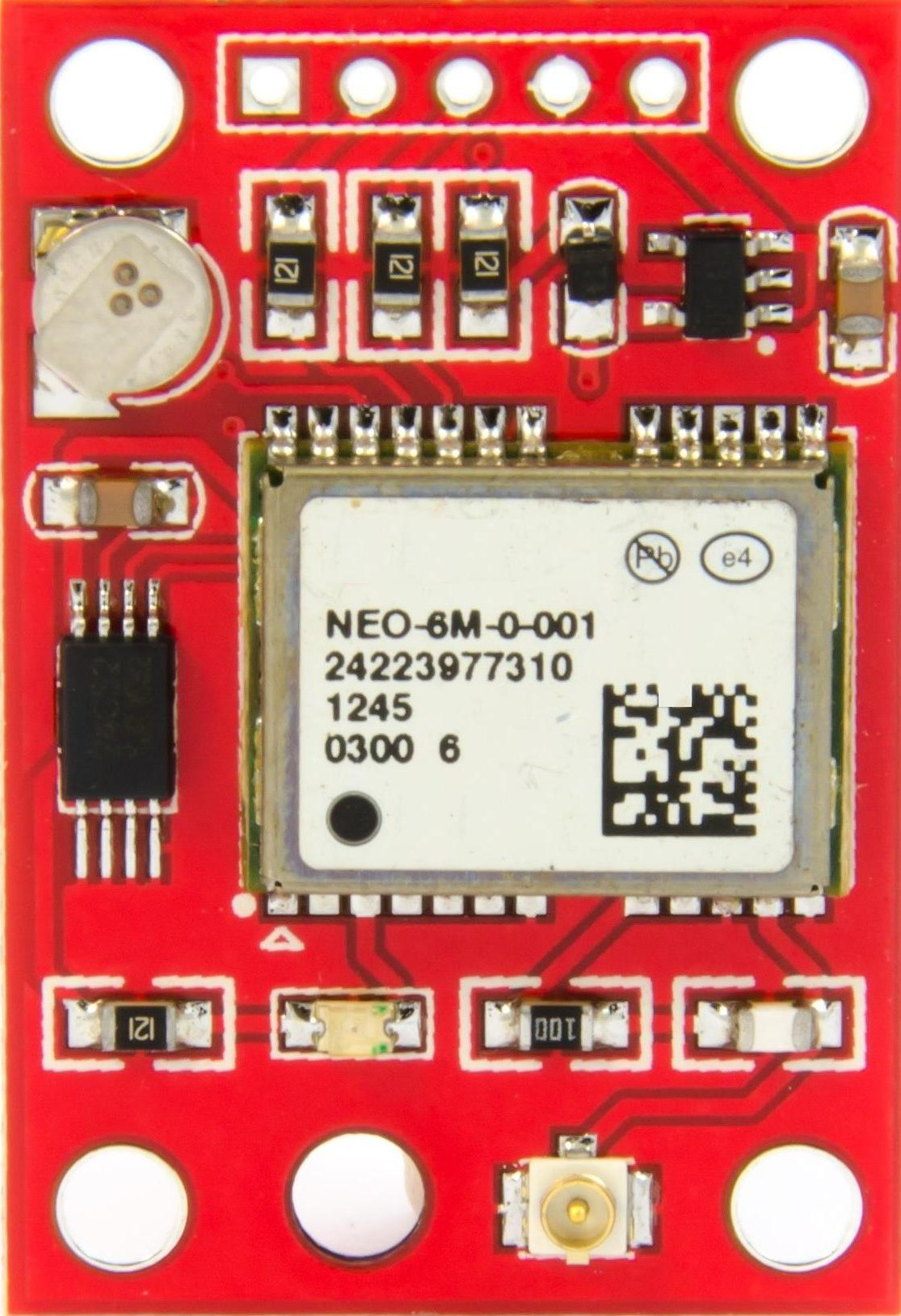
The NEO 6M is a high-performance GPS module designed to provide accurate positioning data. It features a built-in ceramic antenna and supports communication with multiple GPS satellites, ensuring reliable and precise location tracking. The module is compact, lightweight, and easy to integrate into various projects, making it a popular choice for hobbyists and professionals alike.
Explore Projects Built with NEO 6M
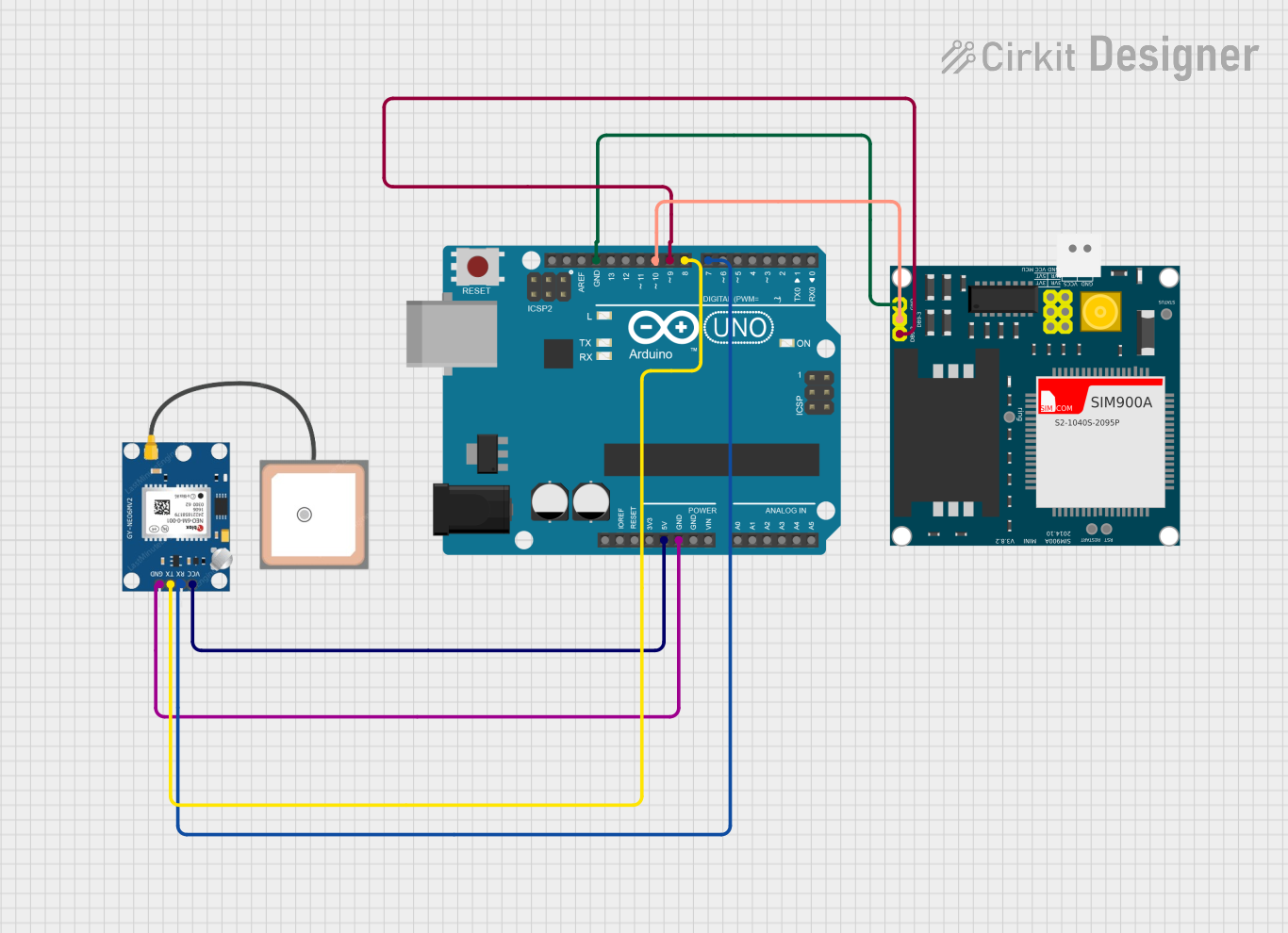
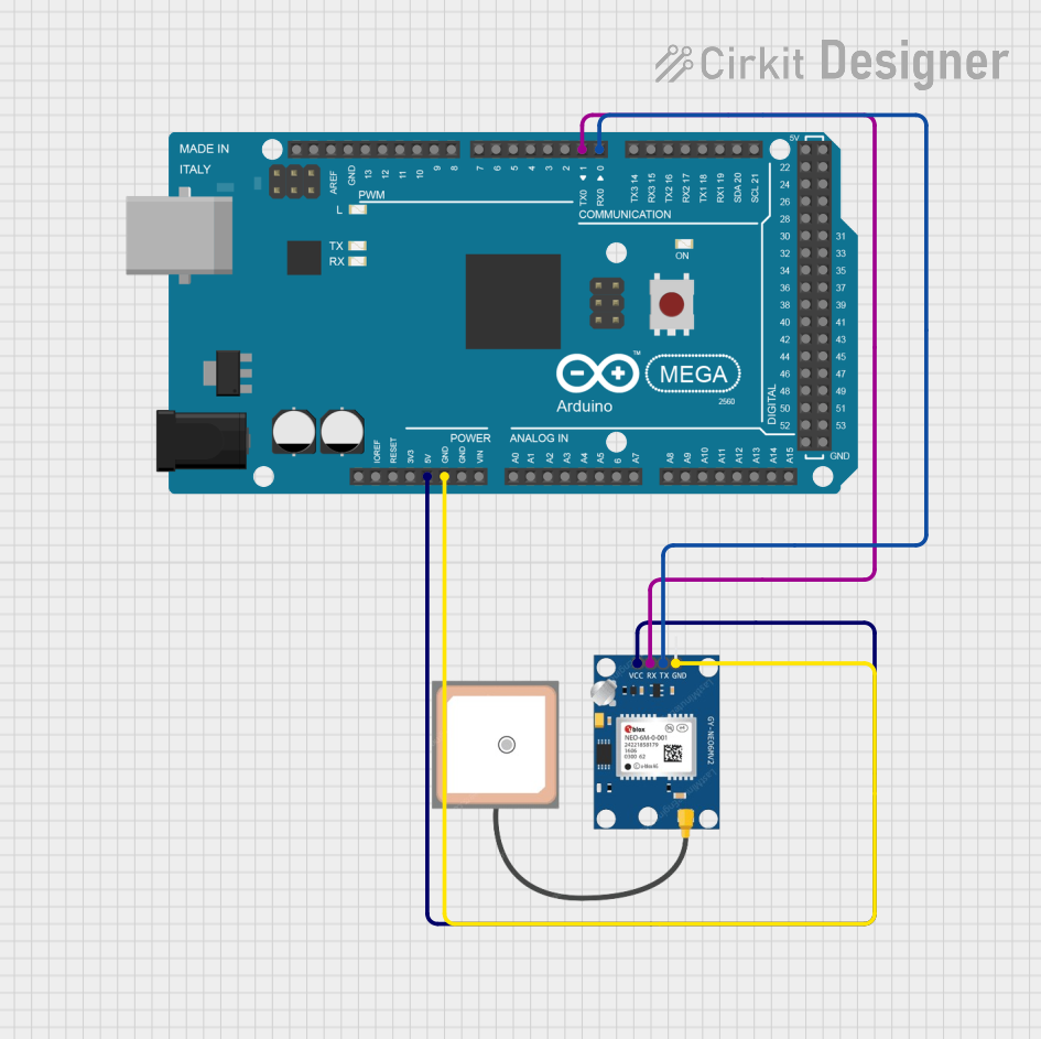
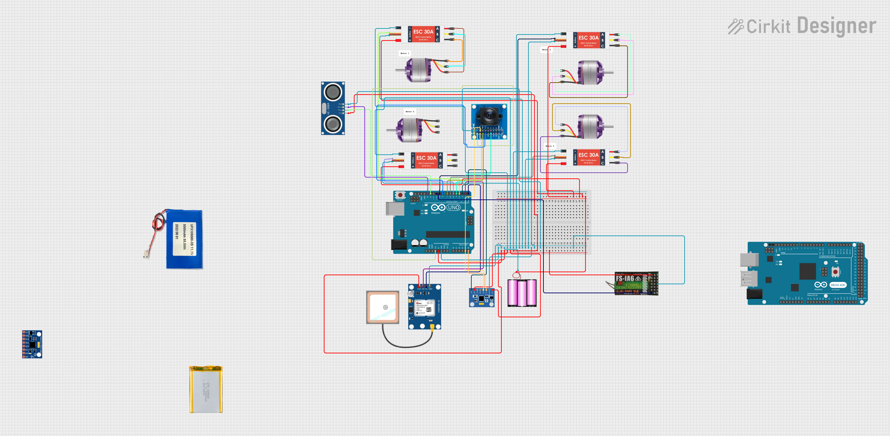
Explore Projects Built with NEO 6M
Common Applications and Use Cases
- Robotics and autonomous vehicles
- Drones and UAV navigation
- Personal tracking devices
- Geographic surveying and mapping
- IoT applications requiring location data
- Navigation systems for vehicles and boats
Technical Specifications
The NEO 6M GPS module is equipped with advanced features to ensure high accuracy and reliability. Below are its key technical details:
Key Technical Details
| Parameter | Specification |
|---|---|
| Operating Voltage | 2.7V to 3.6V (typically 3.3V) |
| Communication Interface | UART (default baud rate: 9600 bps) |
| Position Accuracy | 2.5 meters CEP (Circular Error Probable) |
| Update Rate | 1 Hz (configurable up to 5 Hz) |
| Sensitivity | -161 dBm (tracking), -147 dBm (cold start) |
| Cold Start Time | 27 seconds (typical) |
| Hot Start Time | 1 second (typical) |
| Dimensions | 16 x 12.2 x 2.4 mm |
| Antenna | Built-in ceramic antenna |
Pin Configuration and Descriptions
The NEO 6M module typically comes with a 4-pin interface for easy connection. Below is the pinout description:
| Pin Name | Pin Number | Description |
|---|---|---|
| VCC | 1 | Power supply input (3.3V to 5V) |
| GND | 2 | Ground connection |
| TX | 3 | UART Transmit (data output from module) |
| RX | 4 | UART Receive (data input to module) |
Usage Instructions
The NEO 6M GPS module is straightforward to use and can be easily integrated into microcontroller-based projects, such as those using an Arduino UNO. Below are the steps to get started:
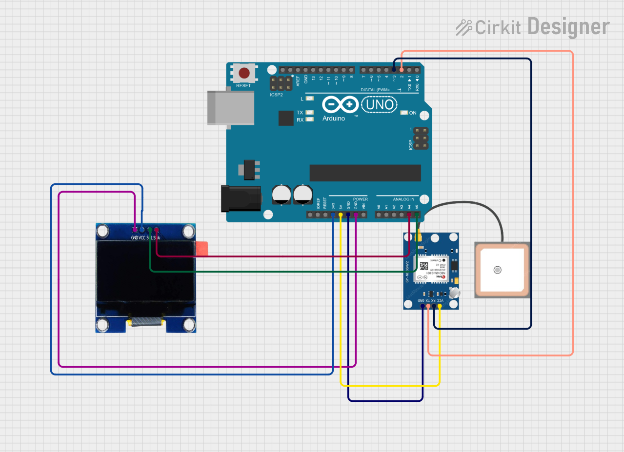
Connecting the NEO 6M to an Arduino UNO
Wiring the Module:
- Connect the
VCCpin of the NEO 6M to the 5V pin on the Arduino UNO. - Connect the
GNDpin of the NEO 6M to the GND pin on the Arduino UNO. - Connect the
TXpin of the NEO 6M to the Arduino's digital pin 4 (or any other pin configured for software serial). - Connect the
RXpin of the NEO 6M to the Arduino's digital pin 3 (or any other pin configured for software serial).
- Connect the
Installing Required Libraries:
- Install the
TinyGPS++library from the Arduino Library Manager. This library simplifies parsing GPS data.
- Install the
Sample Code: Below is an example Arduino sketch to read and display GPS data from the NEO 6M module:
#include <TinyGPS++.h>
#include <SoftwareSerial.h>

// Create a TinyGPS++ object to parse GPS data
TinyGPSPlus gps;

// Define software serial pins for communication with NEO 6M
SoftwareSerial gpsSerial(4, 3); // RX, TX

void setup() {
  Serial.begin(9600); // Initialize serial monitor
  gpsSerial.begin(9600); // Initialize GPS module communication

  Serial.println("NEO 6M GPS Module Test");
}

void loop() {
  // Read data from GPS module
  while (gpsSerial.available() > 0) {
    char c = gpsSerial.read();
    gps.encode(c); // Parse the incoming GPS data

    // If a valid location is available, print it
    if (gps.location.isUpdated()) {
      Serial.print("Latitude: ");
      Serial.print(gps.location.lat(), 6); // Print latitude
      Serial.print(", Longitude: ");
      Serial.println(gps.location.lng(), 6); // Print longitude
    }
  }
}
Important Considerations and Best Practices
- Power Supply: Ensure the module is powered with a stable voltage (3.3V to 5V). Avoid voltage fluctuations to prevent data errors.
- Antenna Placement: For optimal performance, place the module in an open area with a clear view of the sky to maximize satellite reception.
- UART Communication: Avoid connecting the
TXpin of the module directly to a 5V logic level pin. Use a voltage divider or level shifter if necessary. - Cold Start vs. Hot Start: The module may take longer to acquire a GPS fix during a cold start. For faster acquisition, ensure the module has access to previously saved satellite data.
Troubleshooting and FAQs
Common Issues and Solutions
No GPS Fix or Data:
- Cause: Poor satellite reception due to indoor use or obstructions.
- Solution: Move the module to an open area with a clear view of the sky.
Incorrect or Inconsistent Data:
- Cause: Insufficient power supply or unstable voltage.
- Solution: Use a regulated power source and ensure proper connections.
No Communication with Arduino:
- Cause: Incorrect wiring or mismatched baud rates.
- Solution: Double-check the wiring and ensure the baud rate in the code matches the module's default (9600 bps).
Data Overload on Serial Monitor:
- Cause: Excessive data being sent to the serial monitor.
- Solution: Use filters in the code to display only the required data.
FAQs
Q1: Can the NEO 6M work indoors?
A1: While the module can work indoors, its performance may be significantly reduced due to limited satellite visibility. For best results, use it outdoors.
Q2: How can I increase the update rate?
A2: The update rate can be configured up to 5 Hz using specific NMEA commands. Refer to the module's datasheet for details.
Q3: Can I use the NEO 6M with a 5V microcontroller?
A3: Yes, the module supports 5V logic levels on the VCC pin. However, ensure proper level shifting for the RX pin if needed.
Q4: What is the maximum range of the NEO 6M?
A4: The module does not have a range limit as it communicates with GPS satellites. Its accuracy is typically within 2.5 meters CEP.
By following this documentation, you can effectively integrate and troubleshoot the NEO 6M GPS module in your projects.