
How to Use AS608: Examples, Pinouts, and Specs
 Design with AS608 in Cirkit Designer
Introduction
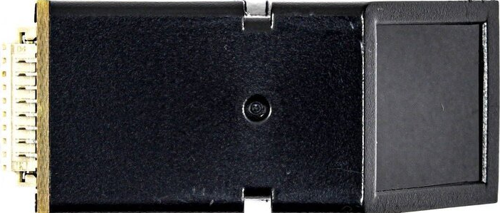
The AS608 is a fingerprint sensor module designed to provide reliable biometric authentication. It features a compact design, high accuracy, and fast fingerprint recognition, making it an ideal choice for security applications. The module is widely used in electronic devices such as access control systems, safes, time attendance systems, and other applications requiring secure user identification.
With its built-in processing capabilities, the AS608 can store and compare fingerprints internally, reducing the need for external processing. Its ease of integration and compatibility with microcontrollers like Arduino make it a popular choice for both hobbyists and professionals.
Explore Projects Built with AS608
 Open Project in Cirkit Designer
 Open Project in Cirkit Designer
 Open Project in Cirkit Designer
 Open Project in Cirkit Designer
Explore Projects Built with AS608
Open Project in Cirkit DesignerOpen Project in Cirkit DesignerOpen Project in Cirkit DesignerOpen Project in Cirkit DesignerTechnical Specifications
The AS608 fingerprint sensor module has the following key technical specifications:
| Parameter | Value |
|---|---|
| Operating Voltage | 3.6V - 6.0V |
| Operating Current | < 120mA |
| Fingerprint Capacity | 128 fingerprints |
| Communication Interface | UART (TTL) |
| Baud Rate | 9600 bps (default, adjustable) |
| Image Resolution | 508 DPI |
| Working Temperature | -20°C to +50°C |
| Dimensions | 20mm x 20mm x 10mm |
Pin Configuration
The AS608 module has a 6-pin interface. The pin configuration is as follows:
| Pin Name | Description |
|---|---|
| VCC | Power supply input (3.6V - 6.0V) |
| GND | Ground |
| TX | UART Transmit (connect to RX of microcontroller) |
| RX | UART Receive (connect to TX of microcontroller) |
| PS | Power Sleep Control (optional, active low) |
| RST | Reset (optional, active low) |
Usage Instructions
Connecting the AS608 to an Arduino UNO
To use the AS608 fingerprint sensor with an Arduino UNO, follow these steps:
Wiring: Connect the AS608 module to the Arduino UNO as shown below:
- VCC → 5V on Arduino
- GND → GND on Arduino
- TX → Pin 2 on Arduino (via a voltage divider to step down 5V to 3.3V)
- RX → Pin 3 on Arduino
- PS and RST can be left unconnected for basic operation.
Install Required Libraries:
- Download and install the
Adafruit Fingerprint Sensor Libraryfrom the Arduino Library Manager.
- Download and install the
Upload Example Code: Use the following example code to enroll and verify fingerprints:
#include <Adafruit_Fingerprint.h>
#include <SoftwareSerial.h>

// Define the pins for SoftwareSerial
SoftwareSerial mySerial(2, 3); // RX, TX

// Initialize the fingerprint sensor
Adafruit_Fingerprint finger(&mySerial);

void setup() {
  Serial.begin(9600); // Initialize serial monitor
  while (!Serial);    // Wait for the serial monitor to open
  Serial.println("AS608 Fingerprint Sensor Test");

  // Initialize the fingerprint sensor
  finger.begin(57600);
  if (finger.verifyPassword()) {
    Serial.println("Fingerprint sensor detected!");
  } else {
    Serial.println("Fingerprint sensor not detected. Check connections.");
    while (1); // Halt the program if the sensor is not detected
  }
}

void loop() {
  Serial.println("Place your finger on the sensor...");
  int result = finger.getImage();
  if (result == FINGERPRINT_OK) {
    Serial.println("Fingerprint image taken successfully.");
  } else if (result == FINGERPRINT_NOFINGER) {
    Serial.println("No finger detected.");
  } else {
    Serial.println("Error capturing fingerprint image.");
  }
  delay(1000); // Wait for 1 second before the next attempt
}
Important Considerations
- Voltage Levels: The AS608 operates at 3.3V logic levels. Use a voltage divider or level shifter when connecting to a 5V microcontroller.
- Baud Rate: Ensure the baud rate of the module matches the settings in your code. The default is 9600 bps.
- Fingerprint Enrollment: Use the provided library's example sketches to enroll fingerprints before attempting verification.
- Power Supply: Provide a stable power supply to avoid erratic behavior.
Troubleshooting and FAQs
Common Issues
Fingerprint Sensor Not Detected:
- Cause: Incorrect wiring or loose connections.
- Solution: Double-check the wiring and ensure the TX and RX pins are correctly connected.
Fingerprint Not Recognized:
- Cause: Poor fingerprint quality or unregistered fingerprint.
- Solution: Ensure the finger is clean and properly placed on the sensor. Enroll the fingerprint again if necessary.
Module Not Responding:
- Cause: Incorrect baud rate or damaged module.
- Solution: Verify the baud rate in the code matches the module's settings. Test with another module if possible.
FAQs
Q1: Can the AS608 store fingerprints permanently?
Yes, the AS608 can store up to 128 fingerprints in its internal memory, which are retained even after power is removed.
Q2: Can I use the AS608 with a Raspberry Pi?
Yes, the AS608 can be used with a Raspberry Pi via its UART interface. Ensure proper voltage level shifting for compatibility.
Q3: How do I adjust the baud rate of the AS608?
The baud rate can be adjusted using specific commands sent to the module. Refer to the AS608 datasheet for details.
Q4: What is the maximum distance for UART communication?
The maximum distance depends on the quality of the wiring and the environment, but it is typically limited to a few meters for reliable communication.
By following this documentation, you can effectively integrate the AS608 fingerprint sensor into your projects and troubleshoot common issues.