How to Use Tps7a4001: Examples, Pinouts, and Specs
Introduction
The TPS7A4001 is a low-dropout (LDO) linear voltage regulator designed to deliver a stable output voltage with low noise and high power supply rejection. It is ideal for high-performance applications requiring precise voltage regulation and noise-sensitive environments. With its wide input voltage range and adjustable output voltage, the TPS7A4001 is versatile and suitable for a variety of use cases.
Explore Projects Built with Tps7a4001


Explore Projects Built with Tps7a4001
Common Applications and Use Cases
- Industrial automation and control systems
- Test and measurement equipment
- Communication infrastructure
- Medical devices
- High-performance analog circuits
- Noise-sensitive applications such as RF systems and audio equipment
Technical Specifications
Key Technical Details
| Parameter | Value |
|---|---|
| Input Voltage Range | 7 V to 100 V |
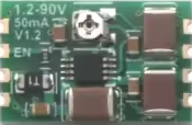
| Output Voltage Range | 1.2 V to 90 V (adjustable) |
| Output Current | Up to 50 mA |
| Dropout Voltage | 350 mV (typical at 50 mA load) |
| Output Voltage Accuracy | ±1% |
| Power Supply Rejection | 72 dB at 1 kHz |
| Quiescent Current | 25 µA (typical) |
| Operating Temperature Range | -40°C to +125°C |
| Package Options | SOT-223, TO-252 |
Pin Configuration and Descriptions
SOT-223 Package Pinout
| Pin Number | Pin Name | Description |
|---|---|---|
| 1 | IN | Input voltage pin. Connect to the power source. |
| 2 | GND | Ground pin. Connect to system ground. |
| 3 | OUT | Regulated output voltage pin. Connect to load. |
| Tab | GND | Thermal pad. Connect to ground for heat dissipation. |
TO-252 Package Pinout
| Pin Number | Pin Name | Description |
|---|---|---|
| 1 | IN | Input voltage pin. Connect to the power source. |
| 2 | GND | Ground pin. Connect to system ground. |
| 3 | OUT | Regulated output voltage pin. Connect to load. |
| Tab | GND | Thermal pad. Connect to ground for heat dissipation. |
Usage Instructions
How to Use the TPS7A4001 in a Circuit
- Input Capacitor: Connect a ceramic capacitor (typically 1 µF or higher) close to the IN pin to stabilize the input voltage and reduce noise.
- Output Capacitor: Use a ceramic capacitor (typically 2.2 µF or higher) at the OUT pin to ensure stable operation and minimize output voltage ripple.
- Adjustable Output Voltage:
- Use an external resistor divider network to set the desired output voltage.
- The output voltage is determined by the formula:
[ V_{OUT} = V_{REF} \times \left(1 + \frac{R_1}{R_2}\right) ] where ( V_{REF} ) is 1.2 V (reference voltage), and ( R_1 ) and ( R_2 ) are the resistors in the divider.
- Thermal Management: Ensure proper heat dissipation by connecting the thermal pad to a large ground plane.
Important Considerations and Best Practices
- Input Voltage: Ensure the input voltage is within the specified range (7 V to 100 V) to avoid damage to the regulator.
- Load Current: Do not exceed the maximum output current of 50 mA.
- Capacitor Selection: Use low-ESR ceramic capacitors for optimal performance.
- PCB Layout: Minimize trace lengths for the IN, OUT, and GND connections to reduce noise and improve stability.
- Thermal Dissipation: Use a heat sink or thermal vias if operating at high input voltages or ambient temperatures.
Example: Connecting TPS7A4001 to an Arduino UNO
The TPS7A4001 can be used to power an Arduino UNO by regulating a high input voltage (e.g., 24 V) down to 5 V. Below is an example circuit and Arduino code:
Circuit Setup
- Connect the input voltage (e.g., 24 V) to the IN pin of the TPS7A4001.
- Connect the OUT pin to the 5 V pin of the Arduino UNO.
- Add a 1 µF capacitor at the IN pin and a 2.2 µF capacitor at the OUT pin.
- Connect the GND pin to the Arduino's GND.
Arduino Code Example
// Example code to blink an LED using Arduino UNO powered by TPS7A4001
// Ensure the TPS7A4001 is providing a stable 5V output to the Arduino

const int ledPin = 13; // Pin connected to the onboard LED

void setup() {
  pinMode(ledPin, OUTPUT); // Set the LED pin as an output
}

void loop() {
  digitalWrite(ledPin, HIGH); // Turn the LED on
  delay(1000);                // Wait for 1 second
  digitalWrite(ledPin, LOW);  // Turn the LED off
  delay(1000);                // Wait for 1 second
}
Troubleshooting and FAQs
Common Issues and Solutions
No Output Voltage:
- Verify that the input voltage is within the specified range (7 V to 100 V).
- Check the connections and ensure the capacitors are properly placed.
- Ensure the resistor divider network is correctly configured for adjustable output.
Output Voltage Instability:
- Use low-ESR ceramic capacitors at the input and output pins.
- Check for excessive noise on the input voltage and add additional filtering if necessary.
- Ensure proper grounding and minimize trace lengths.
Overheating:
- Verify that the input voltage is not excessively high relative to the output voltage.
- Ensure the thermal pad is properly connected to a ground plane for heat dissipation.
- Reduce the load current if possible.
Output Voltage Too Low:
- Check the resistor divider network for incorrect resistor values.
- Verify that the load current does not exceed the regulator's maximum capacity.
FAQs
Q1: Can the TPS7A4001 be used with a battery as the input source?
A1: Yes, the TPS7A4001 can regulate voltage from a battery as long as the input voltage is within the specified range (7 V to 100 V).
Q2: What happens if the input voltage drops below 7 V?
A2: The regulator may stop functioning correctly, and the output voltage may become unstable or drop below the desired level.
Q3: Can I use electrolytic capacitors instead of ceramic capacitors?
A3: While electrolytic capacitors can be used, ceramic capacitors are recommended due to their low ESR and better performance in high-frequency applications.
Q4: Is the TPS7A4001 suitable for powering microcontrollers?
A4: Yes, the TPS7A4001 is suitable for powering microcontrollers, especially in noise-sensitive applications, as it provides a stable and low-noise output voltage.