How to Use Charging Module: Examples, Pinouts, and Specs
Introduction
The Charging Module is a device designed to manage the charging process of batteries, ensuring they are charged safely and efficiently. It typically incorporates features such as overcharge protection, voltage regulation, and current limiting to prevent damage to the battery and extend its lifespan. Charging modules are widely used in portable electronics, power banks, and renewable energy systems.
Explore Projects Built with Charging Module


Explore Projects Built with Charging Module
Common Applications and Use Cases
- Charging lithium-ion or lithium-polymer batteries in portable devices
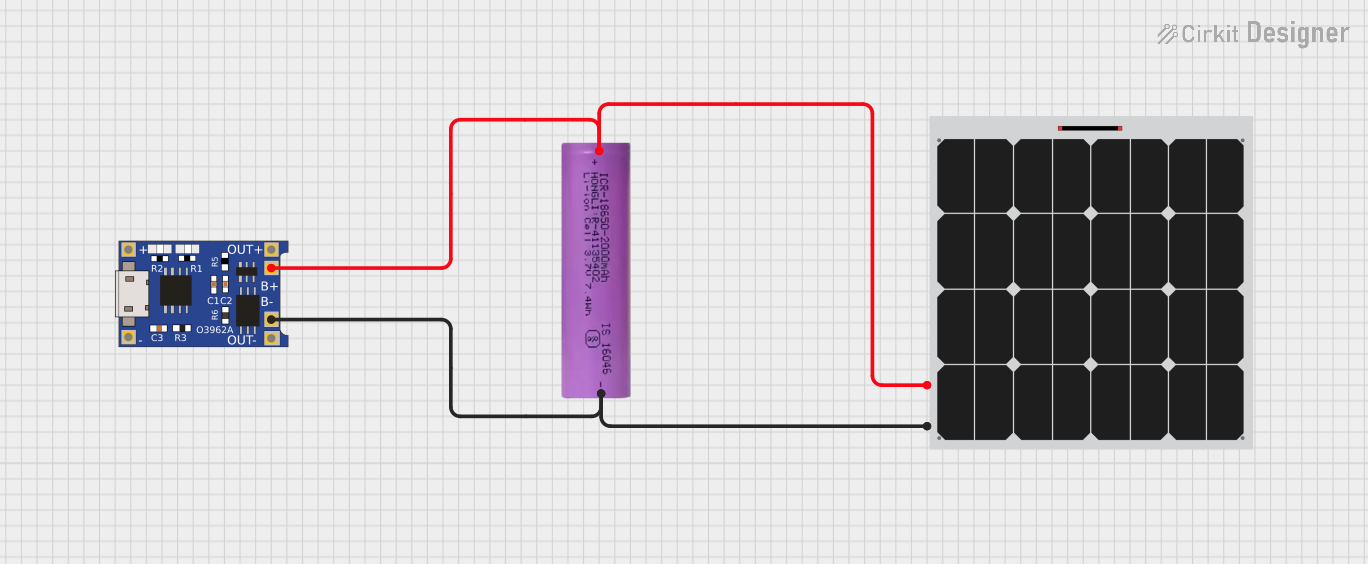
- Power management in solar energy systems
- Battery-powered IoT devices
- DIY electronics projects requiring rechargeable power sources
Technical Specifications
Below are the general technical specifications for a typical charging module. Always refer to the datasheet of your specific module for precise details.
Key Specifications
- Input Voltage Range: 4.5V to 6V (commonly via micro-USB or solder pads)
- Output Voltage: 4.2V (standard for single-cell lithium-ion batteries)
- Charging Current: Adjustable, typically up to 1A
- Overcharge Protection: Stops charging when the battery reaches 4.2V
- Battery Type: Single-cell lithium-ion or lithium-polymer
- LED Indicators: Charging (red), Fully Charged (blue or green)
Pin Configuration and Descriptions
The following table describes the typical pinout of a charging module:
| Pin Name | Description |
|---|---|
VCC |
Input voltage pin (4.5V to 6V). Connect to a power source such as USB or DC. |
GND |
Ground pin. Connect to the ground of the power source and the circuit. |
BAT+ |
Positive terminal for the battery connection. |
BAT- |
Negative terminal for the battery connection. |
OUT+ |
Positive output terminal for powering the load (optional, depending on module). |
OUT- |
Negative output terminal for powering the load (optional, depending on module). |
Usage Instructions
How to Use the Charging Module in a Circuit
Connect the Power Source:
- Connect the
VCCpin to a 5V power source, such as a USB port or a DC adapter. - Connect the
GNDpin to the ground of the power source.
- Connect the
Connect the Battery:
- Attach the positive terminal of the battery to the
BAT+pin. - Attach the negative terminal of the battery to the
BAT-pin. - Ensure the battery is a single-cell lithium-ion or lithium-polymer type.
- Attach the positive terminal of the battery to the
Optional Load Connection:
- If the module supports load sharing, connect the load to the
OUT+andOUT-pins. - This allows the module to power the load while charging the battery.
- If the module supports load sharing, connect the load to the
Monitor the LEDs:
- The red LED indicates the battery is charging.
- The blue or green LED indicates the battery is fully charged.
Important Considerations and Best Practices
- Battery Compatibility: Ensure the battery is a single-cell lithium-ion or lithium-polymer type with a nominal voltage of 3.7V.
- Heat Management: Charging modules can generate heat during operation. Ensure proper ventilation or heat dissipation.
- Current Adjustment: Some modules allow you to adjust the charging current using a resistor. Refer to the module's datasheet for details.
- Avoid Overloading: Do not exceed the module's input voltage or current ratings to prevent damage.
Example: Using the Charging Module with an Arduino UNO
You can use the charging module to power an Arduino UNO via a rechargeable battery. Here's an example:
- Connect the
BAT+andBAT-pins of the charging module to a 3.7V lithium-ion battery. - Connect the
OUT+andOUT-pins to the Arduino'sVINandGNDpins, respectively. - Use the following Arduino code to monitor the battery voltage:
const int batteryPin = A0; // Analog pin connected to battery output
float voltage = 0.0;

void setup() {
  Serial.begin(9600); // Initialize serial communication
}

void loop() {
  int sensorValue = analogRead(batteryPin); // Read analog value
  voltage = sensorValue * (5.0 / 1023.0) * 2;
  // Convert to voltage (assuming a voltage divider is used)

  Serial.print("Battery Voltage: ");
  Serial.print(voltage);
  Serial.println(" V");

  delay(1000); // Wait for 1 second
}
Note: Use a voltage divider circuit if the battery voltage exceeds the Arduino's analog input range (0-5V).
Troubleshooting and FAQs
Common Issues and Solutions
Module Overheating:
- Cause: Excessive input current or poor ventilation.
- Solution: Reduce the charging current or improve heat dissipation.
Battery Not Charging:
- Cause: Incorrect wiring or incompatible battery type.
- Solution: Double-check connections and ensure the battery is a single-cell lithium-ion or lithium-polymer.
LEDs Not Lighting Up:
- Cause: No power input or faulty module.
- Solution: Verify the input voltage and check for module damage.
Load Not Powering:
- Cause: Insufficient output current or incorrect wiring.
- Solution: Ensure the load's current requirement is within the module's capacity.
FAQs
Can I use the charging module with a multi-cell battery?
No, this module is designed for single-cell lithium-ion or lithium-polymer batteries only.What happens if I leave the battery connected after it's fully charged?
The module includes overcharge protection, so it will stop charging the battery once it reaches 4.2V.Can I use the module without a battery?
Some modules support powering a load directly from the input, but this depends on the specific design. Check the datasheet for details.How do I adjust the charging current?
Many modules allow current adjustment by replacing or modifying a resistor. Refer to the module's datasheet for instructions.