
How to Use L298n: Examples, Pinouts, and Specs
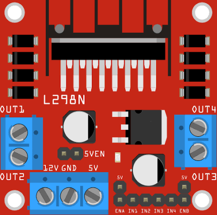
 Design with L298n in Cirkit Designer
Introduction
The L298n is a dual H-bridge motor driver IC designed to control the direction and speed of DC motors and stepper motors. It is capable of driving two motors simultaneously, making it an essential component in robotics, automation, and motor control projects. The L298n can handle high currents and voltages, making it suitable for a wide range of applications, from small hobbyist robots to industrial automation systems.
Explore Projects Built with L298n
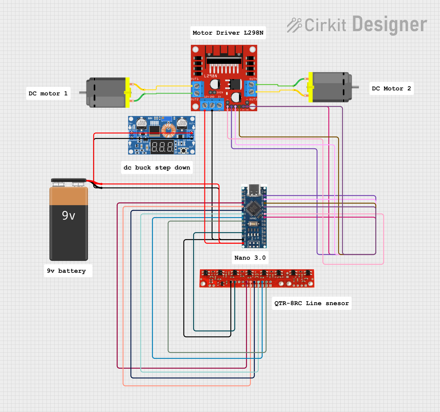 Open Project in Cirkit Designer
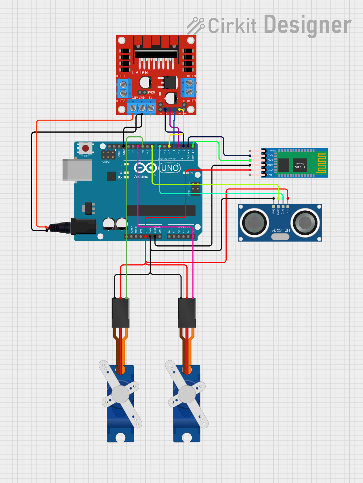 Open Project in Cirkit Designer
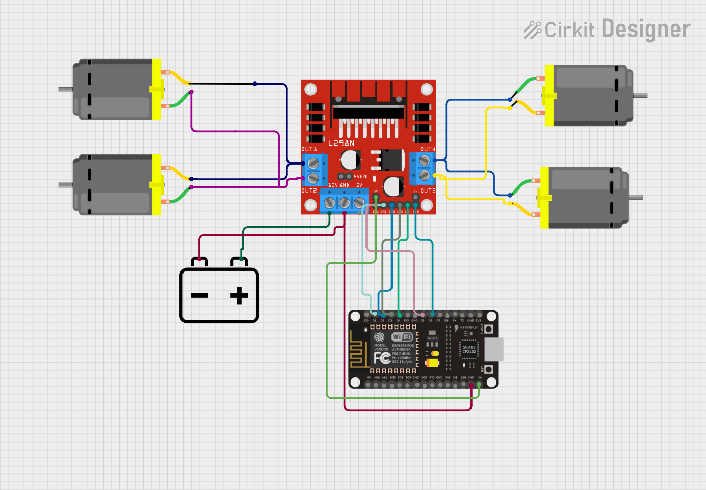 Open Project in Cirkit Designer
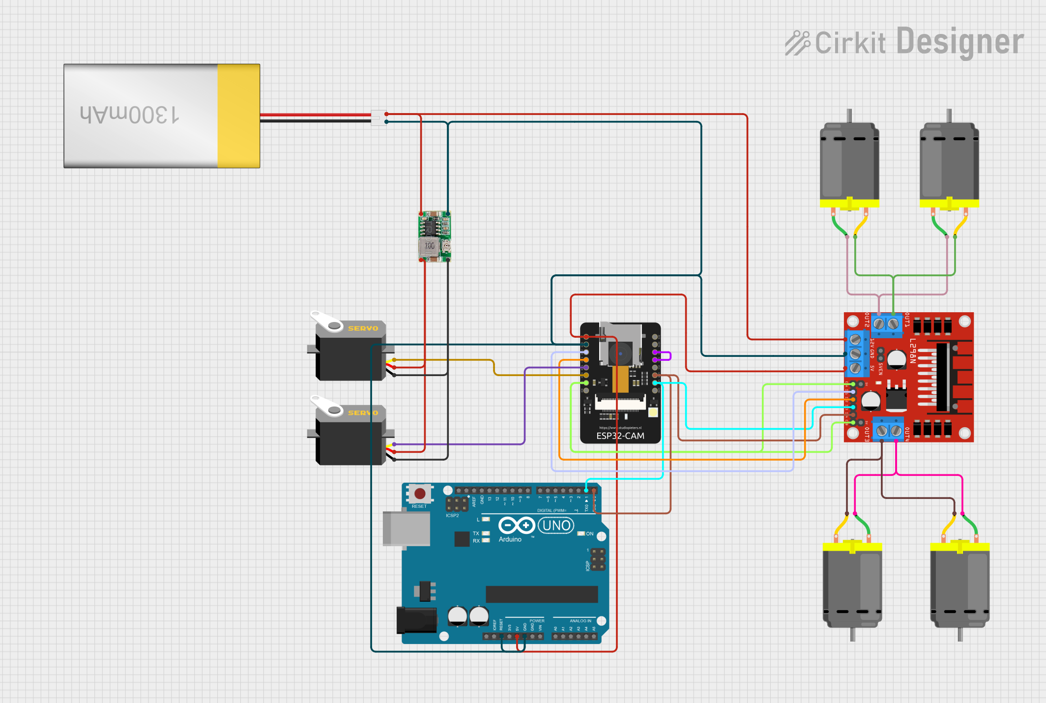 Open Project in Cirkit Designer
Explore Projects Built with L298n
Open Project in Cirkit DesignerOpen Project in Cirkit DesignerOpen Project in Cirkit DesignerOpen Project in Cirkit DesignerCommon Applications:
- Robotics (e.g., controlling wheels or robotic arms)
- Automation systems
- Stepper motor control
- Conveyor belts
- DIY motorized projects
Technical Specifications
The L298n is a robust and versatile motor driver IC. Below are its key technical details:
Key Specifications:
- Operating Voltage: 5V to 46V
- Output Current: Up to 2A per channel (4A total with both channels)
- Logic Voltage: 5V
- Control Logic Levels: High (2.3V to 5V), Low (0V to 1.5V)
- Power Dissipation: 25W (with proper heat sinking)
- Built-in Protection: Thermal shutdown and overcurrent protection
- Number of Channels: 2 (dual H-bridge)
- PWM Frequency: Up to 25 kHz
Pin Configuration and Descriptions:
The L298n IC has 15 pins, but it is often used with a breakout module for easier connections. Below is the pin configuration for the IC:
| Pin Number | Pin Name | Description |
|---|---|---|
| 1 | Enable A | Enables or disables motor A (High = Enabled, Low = Disabled) |
| 2 | Input 1 | Logic input to control motor A direction (works with Input 2) |
| 3 | Output 1 | Output to motor A terminal 1 |
| 4 | Ground (GND) | Ground connection |
| 5 | Ground (GND) | Ground connection |
| 6 | Output 2 | Output to motor A terminal 2 |
| 7 | Input 2 | Logic input to control motor A direction (works with Input 1) |
| 8 | VSS (Logic Supply) | Logic voltage supply (typically 5V) |
| 9 | Enable B | Enables or disables motor B (High = Enabled, Low = Disabled) |
| 10 | Input 3 | Logic input to control motor B direction (works with Input 4) |
| 11 | Output 3 | Output to motor B terminal 1 |
| 12 | Ground (GND) | Ground connection |
| 13 | Ground (GND) | Ground connection |
| 14 | Output 4 | Output to motor B terminal 2 |
| 15 | Input 4 | Logic input to control motor B direction (works with Input 3) |
| 16 | VS (Motor Supply) | Motor voltage supply (up to 46V) |
For the L298n breakout module, additional pins like a 5V regulator jumper and onboard terminals for motor and power connections are included.
Usage Instructions
The L298n can be used to control two DC motors or one stepper motor. Below are the steps to use it in a circuit:
Connecting the L298n:
Power Supply:
- Connect the motor power supply to the
VSpin (or the+12Vterminal on the module). - Connect the logic power supply (5V) to the
VSSpin. - Connect all
GNDpins to the ground of your circuit.
- Connect the motor power supply to the
Motor Connections:
- Connect the terminals of motor A to
Output 1andOutput 2. - Connect the terminals of motor B to
Output 3andOutput 4.
- Connect the terminals of motor A to
Control Pins:
- Use
Input 1andInput 2to control the direction of motor A. - Use
Input 3andInput 4to control the direction of motor B. - Use
Enable AandEnable Bto enable or disable the motors. These pins can also be connected to a PWM signal to control motor speed.
- Use
Optional:
- If using the breakout module, ensure the onboard 5V regulator jumper is set correctly based on your power supply.
Example Code for Arduino UNO:
Below is an example of how to control a DC motor using the L298n and an Arduino UNO:
// Define L298n control pins
const int enableA = 9;  // PWM pin for motor A speed control
const int input1 = 8;   // Direction control pin for motor A
const int input2 = 7;   // Direction control pin for motor A

void setup() {
  // Set control pins as outputs
  pinMode(enableA, OUTPUT);
  pinMode(input1, OUTPUT);
  pinMode(input2, OUTPUT);

  // Initialize motor A to stop
  digitalWrite(input1, LOW);
  digitalWrite(input2, LOW);
  analogWrite(enableA, 0);  // Set speed to 0
}

void loop() {
  // Rotate motor A forward at 50% speed
  digitalWrite(input1, HIGH);
  digitalWrite(input2, LOW);
  analogWrite(enableA, 128);  // 50% duty cycle (128 out of 255)
  delay(2000);  // Run for 2 seconds

  // Rotate motor A backward at full speed
  digitalWrite(input1, LOW);
  digitalWrite(input2, HIGH);
  analogWrite(enableA, 255);  // 100% duty cycle
  delay(2000);  // Run for 2 seconds

  // Stop motor A
  digitalWrite(input1, LOW);
  digitalWrite(input2, LOW);
  analogWrite(enableA, 0);  // Set speed to 0
  delay(2000);  // Wait for 2 seconds
}
Best Practices:
- Use a heat sink with the L298n to prevent overheating during high-current operation.
- Ensure the motor voltage and current ratings are within the L298n's specifications.
- Use decoupling capacitors near the power supply pins to reduce noise.
- For PWM control, use a frequency below 25 kHz for optimal performance.
Troubleshooting and FAQs
Common Issues:
Motor Not Running:
- Check if the
Enablepins are set to HIGH. - Verify the power supply connections and ensure sufficient voltage is provided.
- Ensure the motor connections are correct.
- Check if the
Overheating:
- Attach a heat sink to the L298n IC.
- Reduce the motor load or use motors with lower current requirements.
Erratic Motor Behavior:
- Check for loose connections or poor soldering.
- Add decoupling capacitors to the power supply lines.
PWM Not Controlling Speed:
- Ensure the PWM signal is connected to the
Enablepins. - Verify the PWM frequency is within the L298n's supported range.
- Ensure the PWM signal is connected to the
FAQs:
Q: Can the L298n drive stepper motors?
A: Yes, the L298n can drive bipolar stepper motors by controlling the two H-bridge channels.
Q: What is the maximum current the L298n can handle?
A: The L298n can handle up to 2A per channel, but a heat sink is recommended for high-current applications.
Q: Can I use the L298n with a 3.3V microcontroller?
A: Yes, but you may need level shifters to ensure proper logic level compatibility.
Q: Is the onboard 5V regulator always active on the breakout module?
A: No, the 5V regulator is active only if the jumper is set and the motor supply voltage is above 7V.
By following this documentation, you can effectively use the L298n motor driver in your projects!