How to Use ADC IC: Examples, Pinouts, and Specs
Introduction
The AD7606 is a high-performance, 16-bit Analog-to-Digital Converter (ADC) IC manufactured by Analog Devices. It is designed to convert analog signals into precise digital data, enabling seamless integration of real-world signals into digital systems. The AD7606 is particularly well-suited for applications requiring simultaneous sampling of multiple channels, high accuracy, and robust performance in noisy environments.
Explore Projects Built with ADC IC

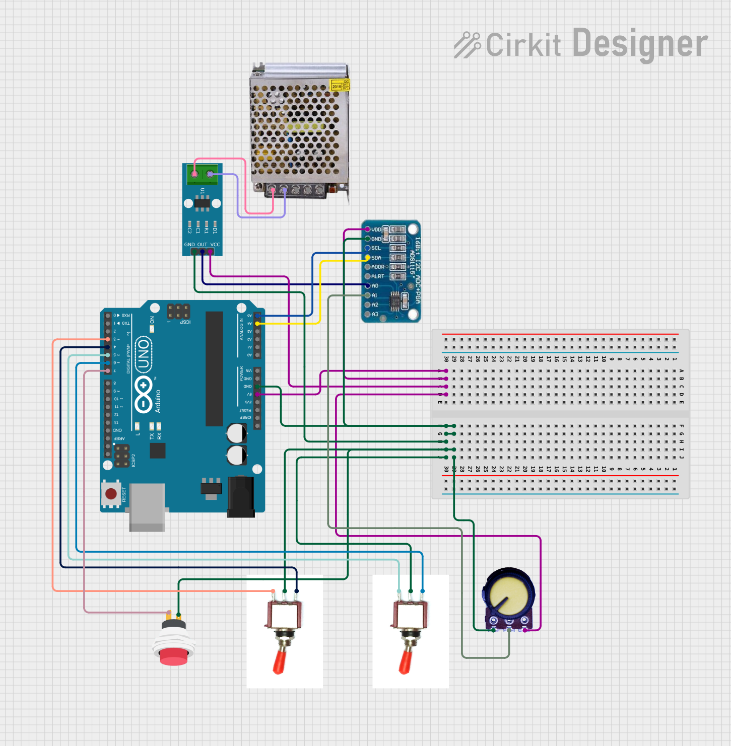
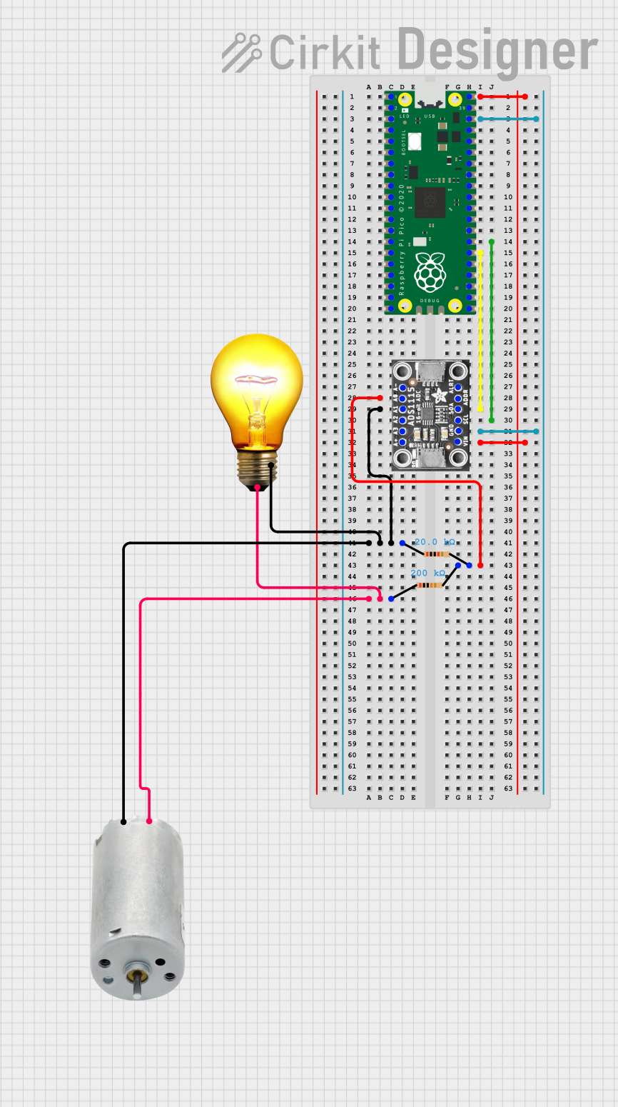

Explore Projects Built with ADC IC
Common Applications and Use Cases
- Data acquisition systems
- Industrial process control
- Power quality monitoring
- Medical instrumentation
- Vibration analysis and condition monitoring
- Motor control systems
Technical Specifications
The AD7606 offers a range of features and specifications that make it a versatile and reliable ADC IC for various applications.
Key Technical Details
| Parameter | Value |
|---|---|
| Resolution | 16-bit |
| Number of Channels | 8 (simultaneous sampling) |
| Input Voltage Range | ±10 V, ±5 V (software-selectable) |
| Sampling Rate | Up to 200 kSPS per channel |
| Power Supply Voltage | 5 V (analog) / 3.3 V or 5 V (digital) |
| Input Impedance | 1 MΩ (typical) |
| Interface | Parallel or Serial (SPI-compatible) |
| Operating Temperature Range | -40°C to +85°C |
| Package Type | LQFP-64 or LFCSP-64 |
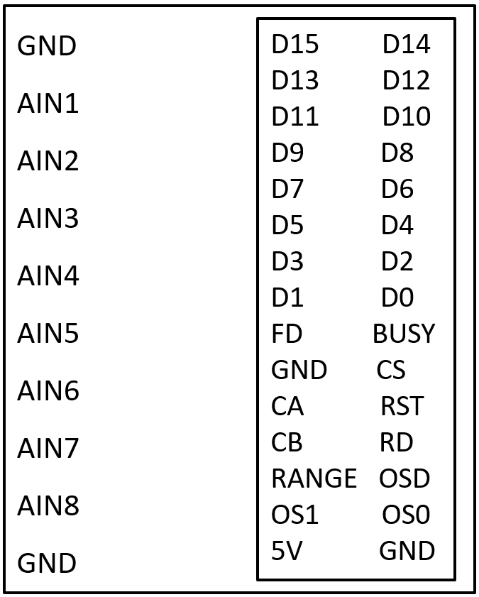
Pin Configuration and Descriptions
The AD7606 has a 64-pin configuration. Below is a summary of key pins and their functions:
Power and Ground Pins
| Pin Name | Description |
|---|---|
| AVCC | Analog power supply (5 V) |
| DVCC | Digital power supply (3.3 V/5 V) |
| AGND | Analog ground |
| DGND | Digital ground |
Analog Input Pins
| Pin Name | Description |
|---|---|
| V1+ to V8+ | Positive analog input channels |
| V1- to V8- | Negative analog input channels |
Control and Interface Pins
| Pin Name | Description |
|---|---|
| CONVST A/B | Conversion start signals for channels A and B |
| BUSY | Indicates ADC conversion status |
| RESET | Resets the ADC |
| CS | Chip select for SPI interface |
| RD | Read enable for parallel interface |
| WR | Write enable for parallel interface |
| SCLK | Serial clock for SPI interface |
| DOUTA/B | Serial data output for channels A and B |
Usage Instructions
The AD7606 is designed for ease of use in a variety of applications. Below are the steps and considerations for integrating the AD7606 into a circuit.
How to Use the AD7606 in a Circuit
Power Supply Connections:
- Connect AVCC to a stable 5 V analog power supply.
- Connect DVCC to a 3.3 V or 5 V digital power supply, depending on your system requirements.
- Ensure proper grounding by connecting AGND and DGND to a common ground plane.
Analog Input Configuration:
- Connect the analog signals to the input pins (V1+ to V8+ and V1- to V8-).
- Select the input voltage range (±10 V or ±5 V) using the RANGE pin or software configuration.
Interface Selection:
- Choose between parallel or serial (SPI) interface based on your system design.
- For SPI, connect SCLK, CS, and DOUTA/B to the corresponding microcontroller pins.
Start Conversion:
- Use the CONVST A/B pins to initiate conversions for the desired channels.
- Monitor the BUSY pin to determine when the conversion is complete.
Read Data:
- For parallel interface, use the RD pin to read data from the data bus.
- For SPI, read data from the DOUTA/B pins using the SCLK signal.
Important Considerations and Best Practices
- Use decoupling capacitors (e.g., 0.1 µF and 10 µF) close to the power supply pins to minimize noise.
- Ensure proper grounding to avoid ground loops and noise interference.
- Use shielded cables for analog inputs in noisy environments.
- Configure the input voltage range and sampling rate according to your application requirements.
Example: Connecting AD7606 to an Arduino UNO (SPI Interface)
Below is an example code snippet for interfacing the AD7606 with an Arduino UNO using the SPI interface:
#include <SPI.h>

// Define SPI pins
const int CS_PIN = 10;  // Chip select pin
const int BUSY_PIN = 9; // Busy pin
const int CONVST_PIN = 8; // Conversion start pin

void setup() {
  // Initialize SPI
  SPI.begin();
  SPI.setDataMode(SPI_MODE0); // SPI mode 0
  SPI.setClockDivider(SPI_CLOCK_DIV16); // Set SPI clock speed

  // Configure pins
  pinMode(CS_PIN, OUTPUT);
  pinMode(BUSY_PIN, INPUT);
  pinMode(CONVST_PIN, OUTPUT);

  // Set initial states
  digitalWrite(CS_PIN, HIGH);
  digitalWrite(CONVST_PIN, LOW);

  Serial.begin(9600); // Initialize serial communication
}

void loop() {
  // Start conversion
  digitalWrite(CONVST_PIN, HIGH);
  delayMicroseconds(1); // Pulse width for CONVST
  digitalWrite(CONVST_PIN, LOW);

  // Wait for conversion to complete
  while (digitalRead(BUSY_PIN) == HIGH);

  // Read data from AD7606
  digitalWrite(CS_PIN, LOW);
  uint16_t adcData = SPI.transfer16(0x0000); // Read 16-bit data
  digitalWrite(CS_PIN, HIGH);

  // Print ADC data
  Serial.println(adcData);

  delay(100); // Delay for next conversion
}
Troubleshooting and FAQs
Common Issues and Solutions
No Output Data:
- Ensure the power supply connections are correct and stable.
- Verify that the CONVST pin is being toggled to start conversions.
- Check the SPI or parallel interface connections.
Incorrect or Noisy Data:
- Verify the input voltage range and ensure the analog signals are within the specified range.
- Use proper grounding and shielding to minimize noise.
- Check for proper decoupling capacitor placement near the power supply pins.
BUSY Pin Stays High:
- Ensure the CONVST pin is being pulsed correctly.
- Check the RESET pin and ensure the ADC is not in a reset state.
FAQs
Q: Can the AD7606 handle single-ended inputs?
A: No, the AD7606 is designed for differential inputs. For single-ended signals, use a differential amplifier to convert them to differential signals.
Q: What is the maximum sampling rate of the AD7606?
A: The AD7606 supports a maximum sampling rate of 200 kSPS per channel.
Q: Can I use the AD7606 with a 3.3 V analog power supply?
A: No, the analog power supply (AVCC) must be 5 V. However, the digital power supply (DVCC) can be 3.3 V or 5 V.
Q: How do I select the input voltage range?
A: The input voltage range (±10 V or ±5 V) can be selected using the RANGE pin or through software configuration.
By following this documentation, users can effectively integrate and utilize the AD7606 ADC IC in their projects.