How to Use RGB Button: Examples, Pinouts, and Specs
Introduction
The RGB Button by Husa is a versatile push-button switch that integrates an RGB LED, allowing it to emit red, green, or blue light (or combinations thereof) based on the input signal. This component is ideal for applications requiring both tactile input and visual feedback, such as user interfaces, control panels, and decorative lighting systems. Its compact design and multi-functionality make it a popular choice for hobbyists and professionals alike.
Explore Projects Built with RGB Button

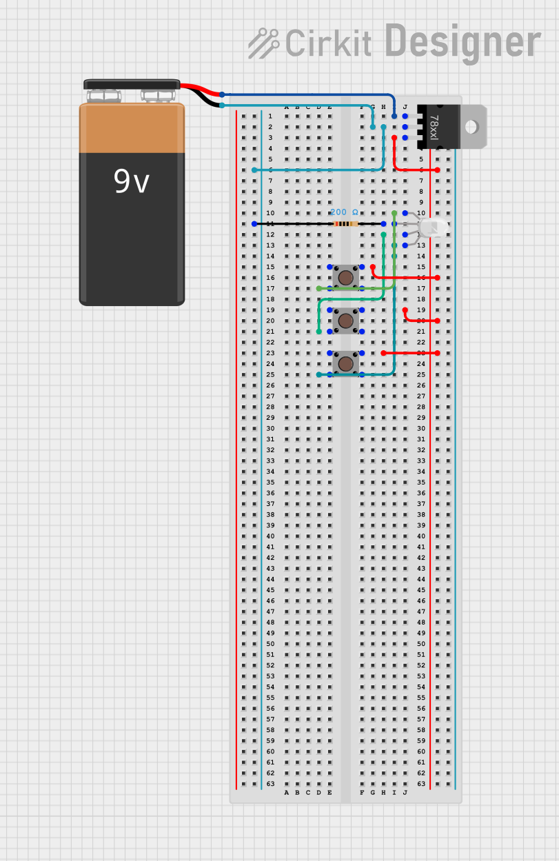
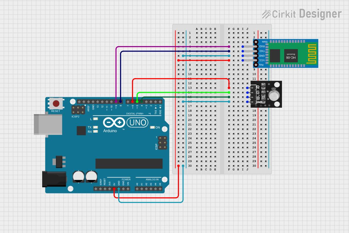
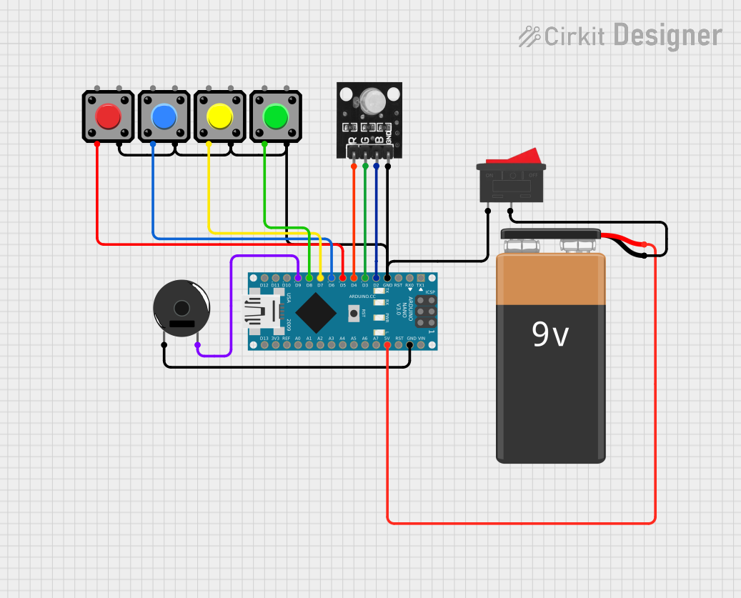
Explore Projects Built with RGB Button
Common Applications
- User interface controls with visual feedback
- Gaming consoles and arcade machines
- Decorative lighting in DIY projects
- Status indicators in control systems
- Educational electronics projects
Technical Specifications
Key Specifications
| Parameter | Value |
|---|---|
| Operating Voltage | 2.0V to 3.3V (per LED color) |
| Forward Current (LED) | 20mA (typical per color) |
| Button Contact Rating | 12V DC, 50mA |
| LED Colors | Red, Green, Blue (RGB) |
| Button Type | Momentary (push-to-make) |
| Dimensions | 12mm x 12mm x 15mm |
| Operating Temperature | -20°C to 70°C |
Pin Configuration and Descriptions
The RGB Button has 6 pins: 3 for the RGB LED and 2 for the button switch. The pinout is as follows:
| Pin Number | Name | Description |
|---|---|---|
| 1 | LED_R | Positive terminal for the Red LED |
| 2 | LED_G | Positive terminal for the Green LED |
| 3 | LED_B | Positive terminal for the Blue LED |
| 4 | GND_LED | Common cathode (negative terminal) for the LED |
| 5 | SW1 | Button terminal 1 |
| 6 | SW2 | Button terminal 2 |
Usage Instructions
How to Use the RGB Button in a Circuit
Connecting the Button:
- Connect SW1 and SW2 to your circuit. When the button is pressed, these pins will be shorted, completing the circuit.
- Use a pull-down resistor (e.g., 10kΩ) on one of the button terminals to ensure a stable low signal when the button is not pressed.
Driving the RGB LED:
- Connect the LED_R, LED_G, and LED_B pins to current-limiting resistors (e.g., 220Ω) to prevent overdriving the LEDs.
- The GND_LED pin should be connected to the ground of your circuit.
- Use a microcontroller (e.g., Arduino) or external switches to control the LED pins and adjust the color output.
Power Requirements:
- Ensure the voltage supplied to the LED pins does not exceed their rated forward voltage (2.0V to 3.3V).
- Use appropriate resistors to limit the current to 20mA per LED color.
Example: Connecting to an Arduino UNO
Below is an example of how to connect and control the RGB Button with an Arduino UNO:
Circuit Connections
- LED_R → Arduino Pin 9 (via 220Ω resistor)
- LED_G → Arduino Pin 10 (via 220Ω resistor)
- LED_B → Arduino Pin 11 (via 220Ω resistor)
- GND_LED → Arduino GND
- SW1 → Arduino Pin 2
- SW2 → Arduino GND
Arduino Code
// Pin definitions for RGB Button
const int buttonPin = 2;  // Button connected to digital pin 2
const int redPin = 9;     // Red LED pin
const int greenPin = 10;  // Green LED pin
const int bluePin = 11;   // Blue LED pin

void setup() {
  pinMode(buttonPin, INPUT_PULLUP); // Set button pin as input with pull-up
  pinMode(redPin, OUTPUT);          // Set red LED pin as output
  pinMode(greenPin, OUTPUT);        // Set green LED pin as output
  pinMode(bluePin, OUTPUT);         // Set blue LED pin as output
}

void loop() {
  // Read the button state
  int buttonState = digitalRead(buttonPin);

  if (buttonState == LOW) { // Button is pressed
    digitalWrite(redPin, HIGH);   // Turn on red LED
    digitalWrite(greenPin, LOW);  // Turn off green LED
    digitalWrite(bluePin, LOW);   // Turn off blue LED
  } else { // Button is not pressed
    digitalWrite(redPin, LOW);    // Turn off red LED
    digitalWrite(greenPin, HIGH); // Turn on green LED
    digitalWrite(bluePin, HIGH);  // Turn on blue LED
  }
}
Important Considerations
- Always use current-limiting resistors for the LED pins to prevent damage.
- Avoid pressing the button with excessive force to ensure longevity.
- If using PWM (Pulse Width Modulation) to control the LED brightness, ensure the frequency is high enough to avoid visible flickering.
Troubleshooting and FAQs
Common Issues and Solutions
LEDs Not Lighting Up:
- Check the polarity of the LED connections. Ensure the GND_LED pin is connected to ground.
- Verify that the current-limiting resistors are correctly sized and connected.
Button Not Responding:
- Ensure the button terminals (SW1 and SW2) are properly connected.
- Check for loose connections or broken wires.
- Use a multimeter to test the continuity of the button when pressed.
Incorrect LED Colors:
- Verify the connections to the LED_R, LED_G, and LED_B pins.
- Ensure the control signals from the microcontroller are correct.
Flickering LEDs:
- If using PWM, increase the frequency to reduce visible flicker.
- Check for unstable power supply or loose connections.
FAQs
Q: Can I use the RGB Button without a microcontroller?
A: Yes, you can use external switches or a simple circuit with resistors to control the LED colors manually.
Q: What is the lifespan of the RGB Button?
A: The button is rated for approximately 100,000 press cycles, and the LEDs have a typical lifespan of 50,000 hours under normal operating conditions.
Q: Can I mix colors with the RGB Button?
A: Yes, by driving multiple LED pins simultaneously, you can create mixed colors like yellow, cyan, magenta, or white.
Q: Is the RGB Button waterproof?
A: No, the RGB Button is not waterproof. Avoid exposing it to moisture or liquids.
This concludes the documentation for the Husa RGB Button. For further assistance, refer to the manufacturer's datasheet or contact technical support.