
How to Use SIK Telemetry Radio: Examples, Pinouts, and Specs
 Design with SIK Telemetry Radio in Cirkit Designer
Introduction
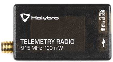
The SIK Telemetry Radio is a wireless communication device designed for transmitting and receiving telemetry data. Manufactured by SIK, this module is widely used in applications requiring real-time data monitoring and control, such as drones, robotics, and remote sensing systems. It operates on a reliable frequency band and provides a robust communication link between devices, making it an essential component for telemetry-based systems.
Explore Projects Built with SIK Telemetry Radio
 Open Project in Cirkit Designer
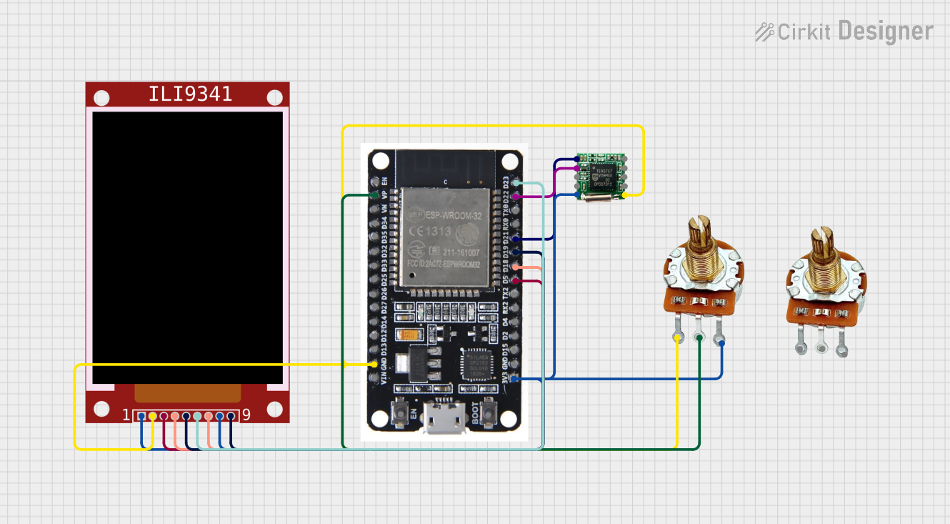 Open Project in Cirkit Designer
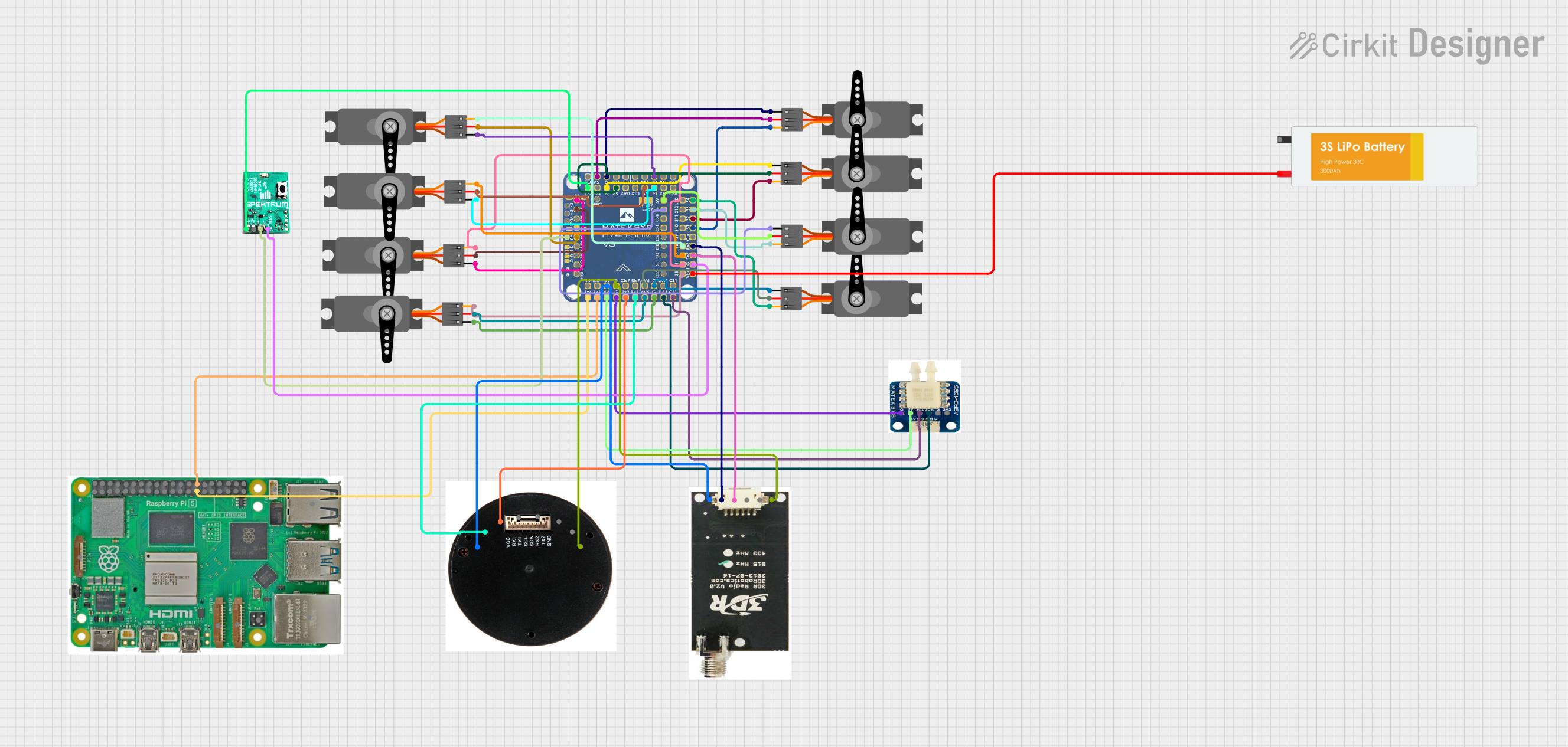 Open Project in Cirkit Designer
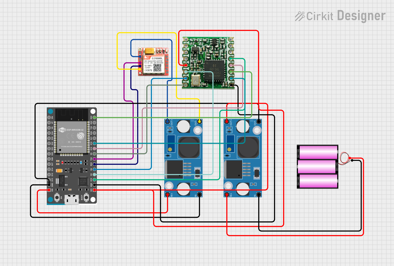 Open Project in Cirkit Designer
Explore Projects Built with SIK Telemetry Radio
Open Project in Cirkit DesignerOpen Project in Cirkit DesignerOpen Project in Cirkit DesignerOpen Project in Cirkit DesignerCommon Applications and Use Cases
- Drones and UAVs: Real-time flight data monitoring and control.
- Robotics: Wireless communication for autonomous robots.
- Remote Sensing: Data transmission from sensors in inaccessible locations.
- IoT Systems: Wireless telemetry for Internet of Things devices.
- Ground Control Stations: Communication between ground stations and aerial vehicles.
Technical Specifications
The SIK Telemetry Radio is available in various configurations, typically consisting of an air module and a ground module. Below are the key technical details:
General Specifications
| Parameter | Value |
|---|---|
| Frequency Band | 433 MHz / 915 MHz (region-specific) |
| Communication Protocol | UART (Serial) |
| Transmission Power | Up to 100 mW (adjustable) |
| Range | Up to 1 km (line of sight) |
| Data Rate | Up to 250 kbps |
| Modulation | GFSK |
| Operating Voltage | 3.3V to 5V |
| Current Consumption | ~100 mA (transmitting) |
| Antenna Connector | RP-SMA |
| Dimensions | ~25 mm x 55 mm |
Pin Configuration and Descriptions
The SIK Telemetry Radio typically uses a 6-pin header for interfacing. Below is the pinout:
| Pin Number | Name | Description |
|---|---|---|
| 1 | GND | Ground connection |
| 2 | 5V | Power input (3.3V to 5V) |
| 3 | TX | Transmit data (connect to RX of host device) |
| 4 | RX | Receive data (connect to TX of host device) |
| 5 | CTS | Clear to Send (optional, for flow control) |
| 6 | RTS | Ready to Send (optional, for flow control) |
Usage Instructions
How to Use the SIK Telemetry Radio in a Circuit
- Power the Module: Connect the
5Vpin to a 3.3V or 5V power source and theGNDpin to ground. - Connect to Host Device:
- Connect the
TXpin of the module to theRXpin of the host device (e.g., Arduino, flight controller). - Connect the
RXpin of the module to theTXpin of the host device.
- Connect the
- Antenna Setup: Attach the provided RP-SMA antenna to the module for optimal signal strength.
- Configure the Module: Use a configuration tool (e.g., Mission Planner for drones) to set the frequency, baud rate, and other parameters.
- Establish Communication: Pair the air module with the ground module. Ensure both modules are configured with the same settings (e.g., frequency and baud rate).
Important Considerations and Best Practices
- Power Supply: Ensure a stable power supply to avoid communication interruptions.
- Antenna Placement: Position the antenna away from metal objects and other electronic components to minimize interference.
- Baud Rate Matching: The baud rate of the telemetry radio must match the baud rate of the host device.
- Line of Sight: For maximum range, maintain a clear line of sight between the air and ground modules.
- Firmware Updates: Periodically update the firmware to ensure compatibility and access to new features.
Example: Connecting to an Arduino UNO
Below is an example of how to use the SIK Telemetry Radio with an Arduino UNO for basic serial communication:
#include <SoftwareSerial.h>

// Define RX and TX pins for the telemetry radio
SoftwareSerial telemetryRadio(10, 11); // RX = Pin 10, TX = Pin 11

void setup() {
  // Initialize serial communication with the telemetry radio
  telemetryRadio.begin(57600); // Set baud rate to match the radio's configuration
  Serial.begin(57600);         // Initialize Serial Monitor at the same baud rate

  Serial.println("SIK Telemetry Radio Test");
}

void loop() {
  // Check if data is available from the telemetry radio
  if (telemetryRadio.available()) {
    char received = telemetryRadio.read(); // Read incoming data
    Serial.print("Received: ");
    Serial.println(received);             // Print data to Serial Monitor
  }

  // Send data to the telemetry radio
  if (Serial.available()) {
    char toSend = Serial.read();          // Read data from Serial Monitor
    telemetryRadio.write(toSend);         // Send data to the telemetry radio
  }
}
Troubleshooting and FAQs
Common Issues and Solutions
No Communication Between Modules
- Cause: Mismatched baud rates or frequency settings.
- Solution: Verify and match the baud rate and frequency settings of both modules using a configuration tool.
Short Communication Range
- Cause: Poor antenna placement or interference.
- Solution: Ensure the antenna is securely connected and positioned away from obstructions or sources of interference.
Module Not Powering On
- Cause: Insufficient power supply.
- Solution: Check the power source and ensure it provides the required voltage and current.
Data Loss or Corruption
- Cause: High data rate or weak signal.
- Solution: Reduce the data rate or improve the line of sight between modules.
FAQs
Q: Can I use the SIK Telemetry Radio with a Raspberry Pi?
- A: Yes, the module can be connected to the UART pins of a Raspberry Pi. Ensure proper voltage levels and configure the serial port accordingly.
Q: What is the maximum range of the SIK Telemetry Radio?
- A: The range can reach up to 1 km in ideal conditions with a clear line of sight.
Q: How do I update the firmware on the SIK Telemetry Radio?
- A: Use a USB-to-serial adapter and a firmware update tool (e.g., Mission Planner) to upload the latest firmware.
Q: Can I use multiple telemetry radios in the same area?
- A: Yes, but ensure each pair operates on a unique frequency to avoid interference.
This concludes the documentation for the SIK Telemetry Radio. For further assistance, refer to the manufacturer's user manual or support resources.