How to Use TB6612 motor driver: Examples, Pinouts, and Specs
Introduction
The TB6612 motor driver is a dual H-bridge motor driver IC designed to control two DC motors or one stepper motor. It enables precise control of motor speed and direction using Pulse Width Modulation (PWM) signals. With its compact design and efficient operation, the TB6612 is widely used in robotics, automation, and other motor control applications. It is particularly popular in projects involving Arduino, Raspberry Pi, and other microcontrollers.
Explore Projects Built with TB6612 motor driver


Explore Projects Built with TB6612 motor driver
Common Applications:
- Robotics (e.g., controlling robot wheels)
- Automated conveyor systems
- Remote-controlled vehicles
- Stepper motor control for CNC machines or 3D printers
- DIY electronics and hobby projects
Technical Specifications
The TB6612 motor driver has the following key technical specifications:
| Parameter | Value |
|---|---|
| Operating Voltage (Vcc) | 2.7V to 5.5V |
| Motor Voltage (VM) | 4.5V to 13.5V |
| Output Current (per channel) | 1.2A (continuous), 3.2A (peak) |
| Control Interface | PWM and digital signals |
| Logic Input Voltage | 0V (Low), 3.3V/5V (High) |
| Operating Temperature | -20°C to +85°C |
| Built-in Protections | Thermal shutdown, overcurrent, and undervoltage lockout |
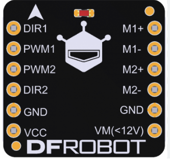
Pin Configuration and Descriptions
The TB6612 motor driver typically comes in a 16-pin package. Below is the pin configuration:
| Pin | Name | Description |
|---|---|---|
| 1 | AIN1 | Input signal for Motor A direction control |
| 2 | AIN2 | Input signal for Motor A direction control |
| 3 | PWMA | PWM input for Motor A speed control |
| 4 | A01 | Output 1 for Motor A |
| 5 | A02 | Output 2 for Motor A |
| 6 | VM | Motor power supply (4.5V to 13.5V) |
| 7 | GND | Ground |
| 8 | Vcc | Logic power supply (2.7V to 5.5V) |
| 9 | STBY | Standby control (High to enable, Low to disable) |
| 10 | BIN1 | Input signal for Motor B direction control |
| 11 | BIN2 | Input signal for Motor B direction control |
| 12 | PWMB | PWM input for Motor B speed control |
| 13 | B01 | Output 1 for Motor B |
| 14 | B02 | Output 2 for Motor B |
| 15 | NC | No connection |
| 16 | NC | No connection |
Usage Instructions
How to Use the TB6612 in a Circuit
Power Connections:
- Connect the
VMpin to the motor power supply (4.5V to 13.5V). - Connect the
Vccpin to the logic power supply (2.7V to 5.5V, typically 3.3V or 5V). - Connect the
GNDpin to the ground of the power supply.
- Connect the
Motor Connections:
- Connect the motor terminals to the
A01andA02pins for Motor A, andB01andB02pins for Motor B.
- Connect the motor terminals to the
Control Signals:
- Use the
AIN1andAIN2pins to control the direction of Motor A, andBIN1andBIN2for Motor B. - Use the
PWMAandPWMBpins to control the speed of Motor A and Motor B, respectively, by providing PWM signals. - Set the
STBYpin HIGH to enable the motor driver.
- Use the
Direction and Speed Control:
- To move a motor forward, set
AIN1HIGH andAIN2LOW (or vice versa for reverse). - Adjust the duty cycle of the PWM signal on
PWMAorPWMBto control the motor speed.
- To move a motor forward, set
Example: Connecting to an Arduino UNO
Below is an example of how to control two DC motors using the TB6612 motor driver and an Arduino UNO:
// Define motor control pins
#define AIN1 7  // Motor A direction control pin 1
#define AIN2 8  // Motor A direction control pin 2
#define PWMA 9  // Motor A speed control (PWM) pin
#define BIN1 10 // Motor B direction control pin 1
#define BIN2 11 // Motor B direction control pin 2
#define PWMB 3  // Motor B speed control (PWM) pin
#define STBY 6  // Standby pin

void setup() {
  // Set motor control pins as outputs
  pinMode(AIN1, OUTPUT);
  pinMode(AIN2, OUTPUT);
  pinMode(PWMA, OUTPUT);
  pinMode(BIN1, OUTPUT);
  pinMode(BIN2, OUTPUT);
  pinMode(PWMB, OUTPUT);
  pinMode(STBY, OUTPUT);

  // Enable the motor driver
  digitalWrite(STBY, HIGH);
}

void loop() {
  // Motor A: Forward at 50% speed
  digitalWrite(AIN1, HIGH);
  digitalWrite(AIN2, LOW);
  analogWrite(PWMA, 128); // 50% duty cycle (128 out of 255)

  // Motor B: Reverse at 75% speed
  digitalWrite(BIN1, LOW);
  digitalWrite(BIN2, HIGH);
  analogWrite(PWMB, 192); // 75% duty cycle (192 out of 255)

  delay(2000); // Run motors for 2 seconds

  // Stop both motors
  analogWrite(PWMA, 0);
  analogWrite(PWMB, 0);

  delay(2000); // Wait for 2 seconds before repeating
}
Important Considerations:
- Ensure that the motor power supply voltage (
VM) matches the requirements of your motors. - Do not exceed the maximum continuous current rating of 1.2A per channel to avoid overheating.
- Use appropriate decoupling capacitors near the
VMandVccpins to reduce noise and ensure stable operation. - If the motors draw high current, consider adding heat sinks to the TB6612 IC for better thermal management.
Troubleshooting and FAQs
Common Issues and Solutions
Motors Not Running:
- Ensure the
STBYpin is set HIGH to enable the motor driver. - Verify that the power supply connections (
VM,Vcc, andGND) are correct and stable.
- Ensure the
Motor Running in the Wrong Direction:
- Check the logic levels on the direction control pins (
AIN1,AIN2,BIN1,BIN2). - Reverse the motor connections if necessary.
- Check the logic levels on the direction control pins (
Motor Speed Not Changing:
- Ensure that a valid PWM signal is being sent to the
PWMAorPWMBpins. - Verify the duty cycle of the PWM signal using an oscilloscope or multimeter.
- Ensure that a valid PWM signal is being sent to the
Overheating:
- Check if the motor current exceeds the maximum rating of 1.2A per channel.
- Add heat sinks or improve ventilation around the TB6612 IC.
FAQs
Q: Can the TB6612 control stepper motors?
A: Yes, the TB6612 can control a bipolar stepper motor by using both H-bridge channels. You will need to sequence the control signals appropriately.
Q: Is the TB6612 compatible with 3.3V logic?
A: Yes, the TB6612 is compatible with both 3.3V and 5V logic levels.
Q: Can I use the TB6612 with a single motor?
A: Yes, you can use one H-bridge channel to control a single motor, leaving the other channel unused.
Q: What happens if the motor draws more than 1.2A?
A: The TB6612 has built-in overcurrent protection, but prolonged overcurrent conditions may cause the IC to overheat or shut down. Use motors within the specified current limits.