How to Use IR Receiver : Examples, Pinouts, and Specs
Introduction
An IR Receiver is a device that detects infrared (IR) signals, typically used in remote control applications. It converts the received infrared light signals into electrical signals that can be processed by a microcontroller or other electronic circuits. IR Receivers are commonly found in consumer electronics such as TVs, air conditioners, and audio systems, enabling wireless communication between a remote control and the device.
Explore Projects Built with IR Receiver


Explore Projects Built with IR Receiver
Common Applications and Use Cases
- Remote control systems for TVs, set-top boxes, and home appliances
- Wireless data transmission
- Proximity sensors
- IR-based communication between devices
- Robotics and automation systems
Technical Specifications
Below are the general technical specifications for a typical IR Receiver module (e.g., TSOP1738 or similar):
| Parameter | Value |
|---|---|
| Operating Voltage | 2.7V to 5.5V |
| Operating Current | 0.4mA to 1.5mA |
| Carrier Frequency | 38kHz (common), 36kHz, or 40kHz |
| Reception Angle | ±45° |
| Maximum Range | 10-15 meters (depending on IR LED) |
| Output Signal | Digital (active low) |
| Response Time | 400µs to 600µs |
| Ambient Light Resistance | Up to 500 lux |
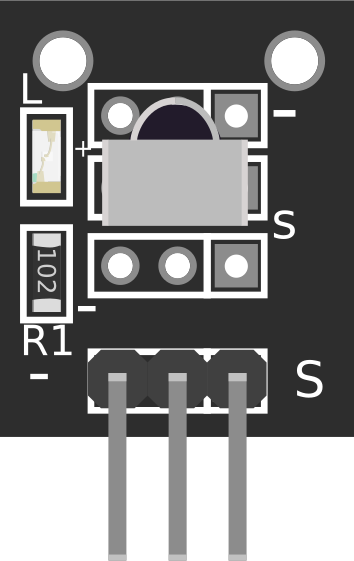
Pin Configuration and Descriptions
The IR Receiver module typically has three pins. Below is the pinout description:
| Pin | Name | Description |
|---|---|---|
| 1 | VCC | Power supply pin. Connect to 3.3V or 5V depending on the module specifications. |
| 2 | GND | Ground pin. Connect to the ground of the circuit. |
| 3 | OUT | Digital output pin. Outputs a low signal when IR is detected. |
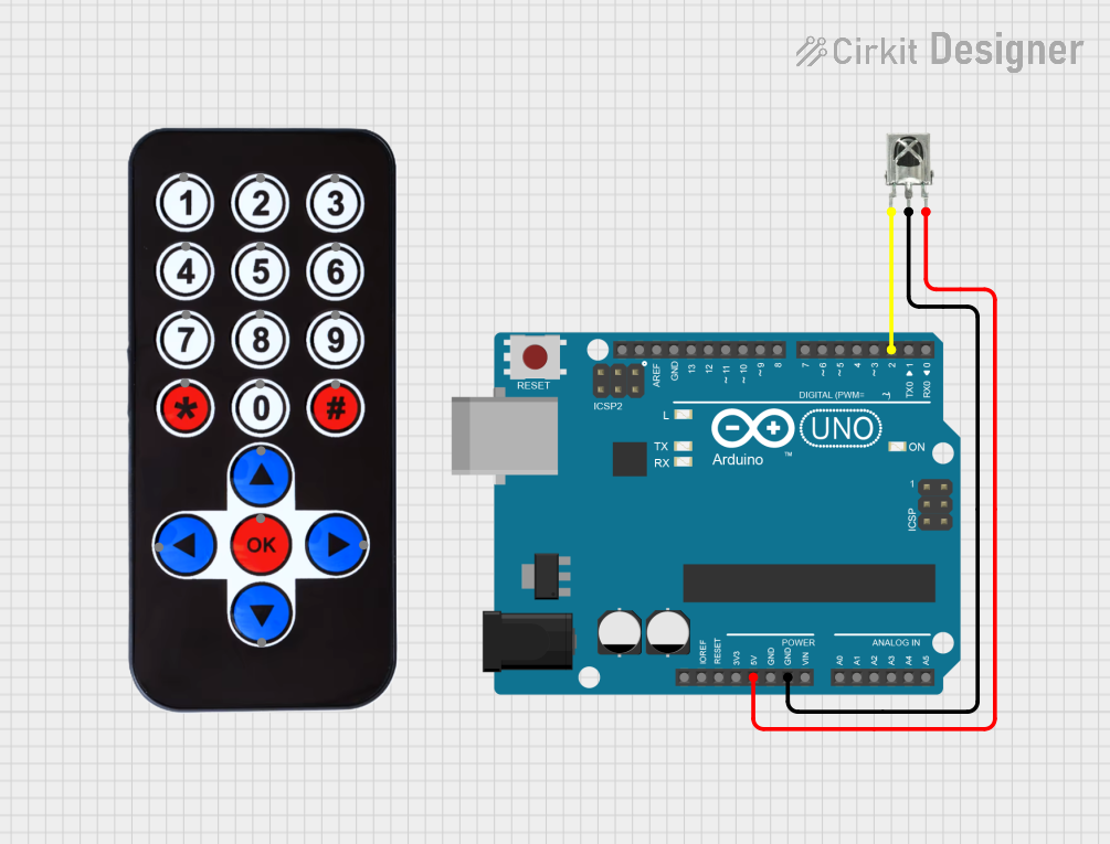
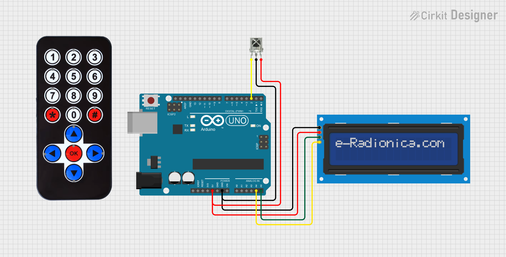
Usage Instructions
How to Use the IR Receiver in a Circuit
Connect the Pins:
- Connect the
VCCpin to a 3.3V or 5V power supply. - Connect the
GNDpin to the ground of your circuit. - Connect the
OUTpin to a digital input pin of your microcontroller (e.g., Arduino).
- Connect the
Place the IR Receiver:
- Ensure the IR Receiver is positioned to face the IR transmitter (e.g., remote control).
- Avoid obstructions between the transmitter and receiver.
Add a Pull-Up Resistor:
- If the output signal is unstable, connect a pull-up resistor (e.g., 10kΩ) between the
OUTpin andVCC.
- If the output signal is unstable, connect a pull-up resistor (e.g., 10kΩ) between the
Filter Ambient Light:
- Use the IR Receiver in an environment with minimal ambient IR interference (e.g., direct sunlight).
Arduino UNO Example Code
Below is an example of how to use an IR Receiver with an Arduino UNO to decode signals from a remote control:
#include <IRremote.h> // Include the IRremote library

const int RECV_PIN = 2; // Define the pin connected to the IR Receiver's OUT pin
IRrecv irrecv(RECV_PIN); // Create an IRrecv object
decode_results results;  // Create a variable to store decoded results

void setup() {
  Serial.begin(9600); // Initialize serial communication for debugging
  irrecv.enableIRIn(); // Start the IR Receiver
  Serial.println("IR Receiver is ready to decode signals.");
}

void loop() {
  if (irrecv.decode(&results)) { // Check if a signal is received
    Serial.print("Received IR code: ");
    Serial.println(results.value, HEX); // Print the received code in hexadecimal
    irrecv.resume(); // Prepare to receive the next signal
  }
}
Important Considerations and Best Practices
- Power Supply: Ensure the IR Receiver is powered with the correct voltage (3.3V or 5V).
- Signal Decoding: Use an appropriate library (e.g., IRremote) to decode the received signals.
- Interference: Minimize interference from ambient light or other IR sources.
- Distance and Alignment: Ensure the IR transmitter is within the receiver's range and properly aligned.
Troubleshooting and FAQs
Common Issues and Solutions
No Signal Detected:
- Cause: Incorrect wiring or loose connections.
- Solution: Double-check the connections and ensure the
OUTpin is connected to the correct microcontroller pin.
Unstable Output:
- Cause: Electrical noise or lack of a pull-up resistor.
- Solution: Add a pull-up resistor (e.g., 10kΩ) between the
OUTpin andVCC.
Short Range:
- Cause: Weak IR transmitter or misalignment.
- Solution: Ensure the IR transmitter is aligned and within the receiver's range.
Interference from Ambient Light:
- Cause: Strong ambient IR sources (e.g., sunlight or fluorescent lights).
- Solution: Use the IR Receiver in a controlled environment or shield it from ambient light.
FAQs
Q1: Can I use the IR Receiver with a 3.3V microcontroller?
A1: Yes, most IR Receivers operate within a voltage range of 2.7V to 5.5V. Check the datasheet of your specific module to confirm compatibility.
Q2: How do I know the carrier frequency of my remote control?
A2: Most consumer remotes use a 38kHz carrier frequency. If unsure, consult the remote's documentation or test it with an IR Receiver.
Q3: Why is the output signal always low?
A3: This could indicate constant IR interference or a faulty module. Check for ambient IR sources and ensure the module is functioning correctly.
Q4: Can I use multiple IR Receivers in the same circuit?
A4: Yes, but ensure they are positioned to avoid interference from each other. Use separate microcontroller pins for each receiver.
By following this documentation, you can effectively integrate an IR Receiver into your projects for remote control and wireless communication applications.