How to Use 2inch OLED Display 240x320RGB ST7789: Examples, Pinouts, and Specs
Introduction
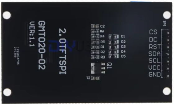
The 2-inch OLED Display 240x320RGB ST7789 (Manufacturer Part ID: GMT020-02-7P) by Diyuser is a compact, high-resolution display module designed for embedded systems and DIY projects. Featuring a resolution of 240x320 pixels and full RGB color support, this display is powered by the ST7789 controller, which ensures smooth rendering and efficient communication with microcontrollers. Its small form factor and vibrant visuals make it ideal for applications such as portable devices, IoT dashboards, and graphical user interfaces.
Explore Projects Built with 2inch OLED Display 240x320RGB ST7789


Explore Projects Built with 2inch OLED Display 240x320RGB ST7789
Common Applications
- Portable electronic devices
- IoT dashboards and smart home displays
- Wearable technology
- Embedded systems requiring graphical output
- DIY projects and prototyping
Technical Specifications
Key Technical Details
| Parameter | Value |
|---|---|
| Display Type | OLED |
| Resolution | 240x320 pixels |
| Color Support | RGB (65K colors) |
| Controller IC | ST7789 |
| Interface | SPI (4-wire) |
| Operating Voltage | 3.3V |
| Logic Level | 3.3V |
| Power Consumption | ~50mW |
| Dimensions | 2 inches (diagonal) |
| Operating Temperature | -20°C to 70°C |
Pin Configuration and Descriptions
The display module has a 7-pin interface for communication and power. Below is the pinout:
| Pin Number | Pin Name | Description |
|---|---|---|
| 1 | GND | Ground connection |
| 2 | VCC | Power supply (3.3V) |
| 3 | SCL | Serial Clock Line for SPI communication |
| 4 | SDA | Serial Data Line for SPI communication |
| 5 | RES | Reset pin (active low) |
| 6 | DC | Data/Command control pin |
| 7 | CS | Chip Select (active low) |
Usage Instructions
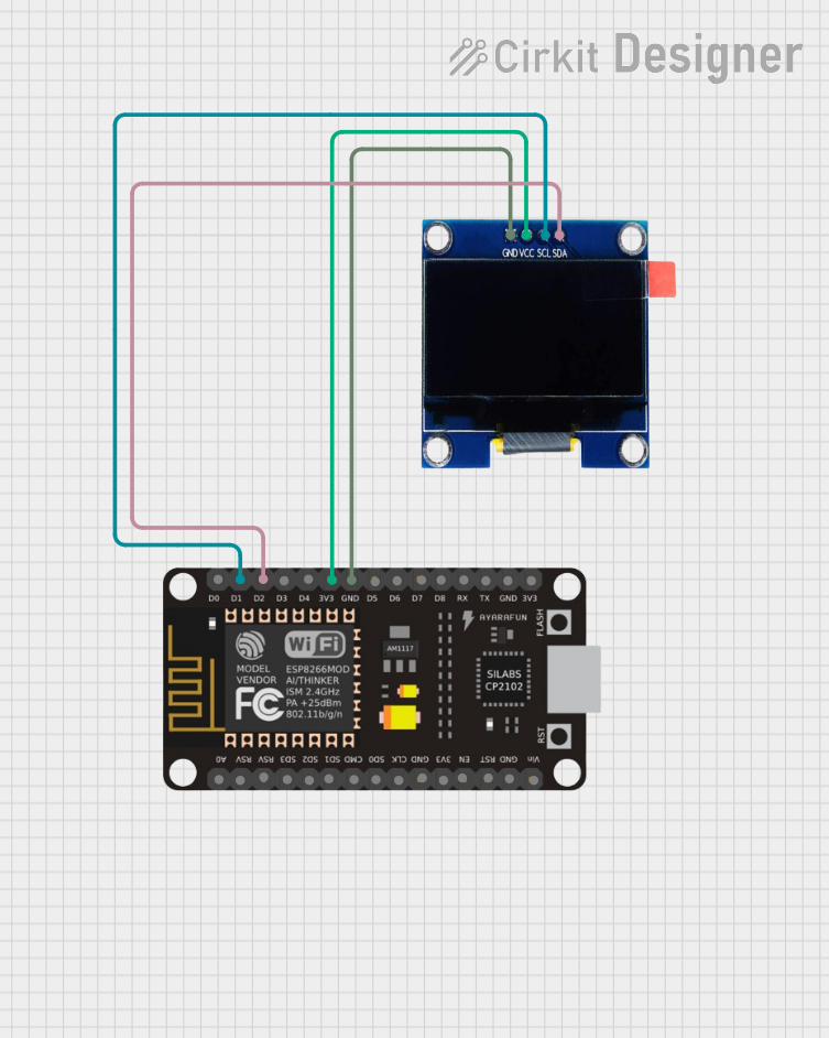
How to Use the Component in a Circuit
- Power Supply: Connect the
VCCpin to a 3.3V power source and theGNDpin to ground. - SPI Communication: Connect the
SCL(clock) andSDA(data) pins to the corresponding SPI pins on your microcontroller. - Control Pins:
- Connect the
RESpin to a GPIO pin on your microcontroller for resetting the display. - Use the
DCpin to toggle between data and command modes. - Connect the
CSpin to a GPIO pin to enable or disable the display module.
- Connect the
- Initialization: Use the ST7789 driver library or write custom initialization code to configure the display.
Important Considerations
- Ensure the logic level of your microcontroller matches the display's 3.3V requirement. Use a level shifter if your microcontroller operates at 5V.
- Avoid prolonged exposure to extreme temperatures to maintain display longevity.
- Use decoupling capacitors near the power pins to reduce noise and ensure stable operation.
Example Code for Arduino UNO
Below is an example of how to interface the display with an Arduino UNO using the Adafruit ST7789 library. Note that the Arduino UNO operates at 5V, so a level shifter is required.
#include <Adafruit_GFX.h>     // Core graphics library
#include <Adafruit_ST7789.h>  // ST7789 driver library
#include <SPI.h>

// Define pin connections
#define TFT_CS    10  // Chip Select pin
#define TFT_RST   9   // Reset pin
#define TFT_DC    8   // Data/Command pin

// Initialize the display object
Adafruit_ST7789 tft = Adafruit_ST7789(TFT_CS, TFT_DC, TFT_RST);

void setup() {
  // Initialize serial communication for debugging
  Serial.begin(9600);
  Serial.println("Initializing display...");

  // Initialize the display
  tft.init(240, 320);  // Initialize with 240x320 resolution
  tft.setRotation(1);  // Set display orientation (1 = landscape)

  // Fill the screen with a solid color
  tft.fillScreen(ST77XX_BLACK);

  // Display a message
  tft.setTextColor(ST77XX_WHITE);
  tft.setTextSize(2);
  tft.setCursor(10, 10);
  tft.println("Hello, World!");
}

void loop() {
  // Add your main code here
}
Troubleshooting and FAQs
Common Issues and Solutions
Display Not Turning On:
- Verify the power connections (
VCCandGND). - Ensure the
CSpin is correctly configured and set low to enable the display.
- Verify the power connections (
No Output or Garbled Display:
- Check the SPI connections (
SCLandSDA) for loose or incorrect wiring. - Ensure the
DCandRESpins are properly connected and configured in the code. - Confirm that the ST7789 library is correctly installed and initialized.
- Check the SPI connections (
Flickering or Unstable Display:
- Add decoupling capacitors (e.g., 0.1µF) near the power pins to reduce noise.
- Verify that the power supply provides a stable 3.3V output.
Arduino UNO Compatibility Issues:
- Use a level shifter to convert the 5V logic level of the Arduino UNO to 3.3V.
- Double-check the pin assignments in the code to match your wiring.
FAQs
Q: Can this display be used with 5V microcontrollers?
A: Yes, but you must use a level shifter to convert the 5V logic signals to 3.3V.
Q: What is the maximum frame rate supported by the display?
A: The frame rate depends on the SPI clock speed and the microcontroller's processing power. Typically, it can achieve up to 60 FPS with optimized code.
Q: Is there a backlight control for this display?
A: No, as an OLED display, it does not require a backlight. Each pixel emits its own light.
Q: Can I use this display with Raspberry Pi?
A: Yes, the display is compatible with Raspberry Pi. Use the SPI interface and appropriate libraries (e.g., luma.oled or Adafruit-ST7789).
This concludes the documentation for the 2-inch OLED Display 240x320RGB ST7789. For further assistance, refer to the manufacturer's datasheet or community forums.