
How to Use GPS NEO-M8N: Examples, Pinouts, and Specs
 Design with GPS NEO-M8N in Cirkit Designer
Introduction
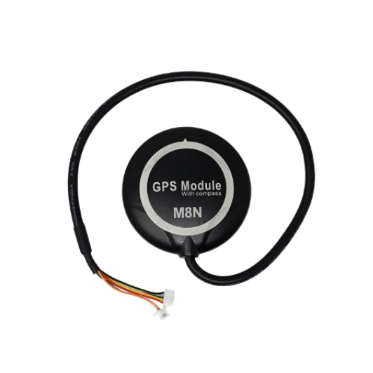
The GPS NEO-M8N is a high-performance GPS module designed to provide accurate positioning and timing information. It supports multiple Global Navigation Satellite Systems (GNSS), including GPS, GLONASS, Galileo, and BeiDou, ensuring robust and reliable location tracking. This module is widely used in applications such as navigation systems, robotics, drones, and Internet of Things (IoT) devices. Its compact size, low power consumption, and high sensitivity make it an ideal choice for both hobbyists and professionals.
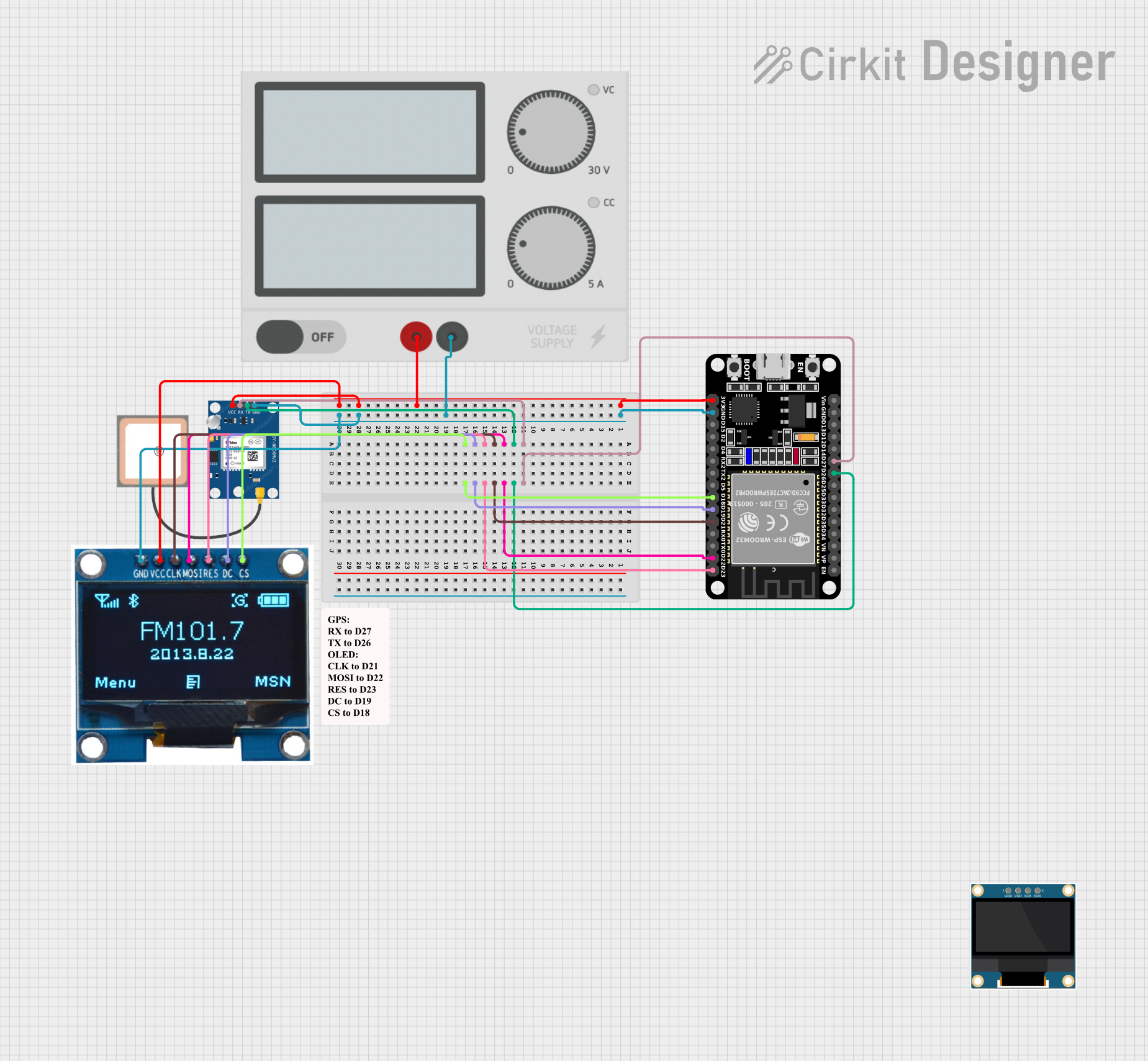
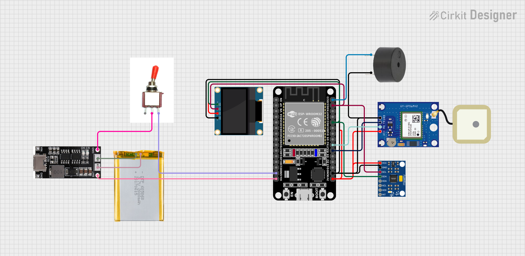
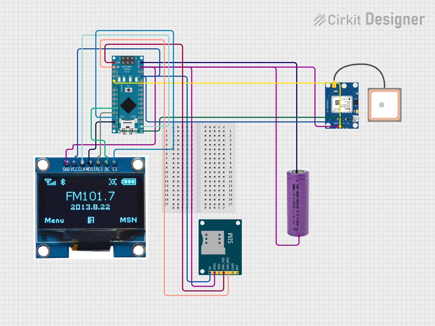
Explore Projects Built with GPS NEO-M8N
 Open Project in Cirkit Designer
 Open Project in Cirkit Designer
 Open Project in Cirkit Designer
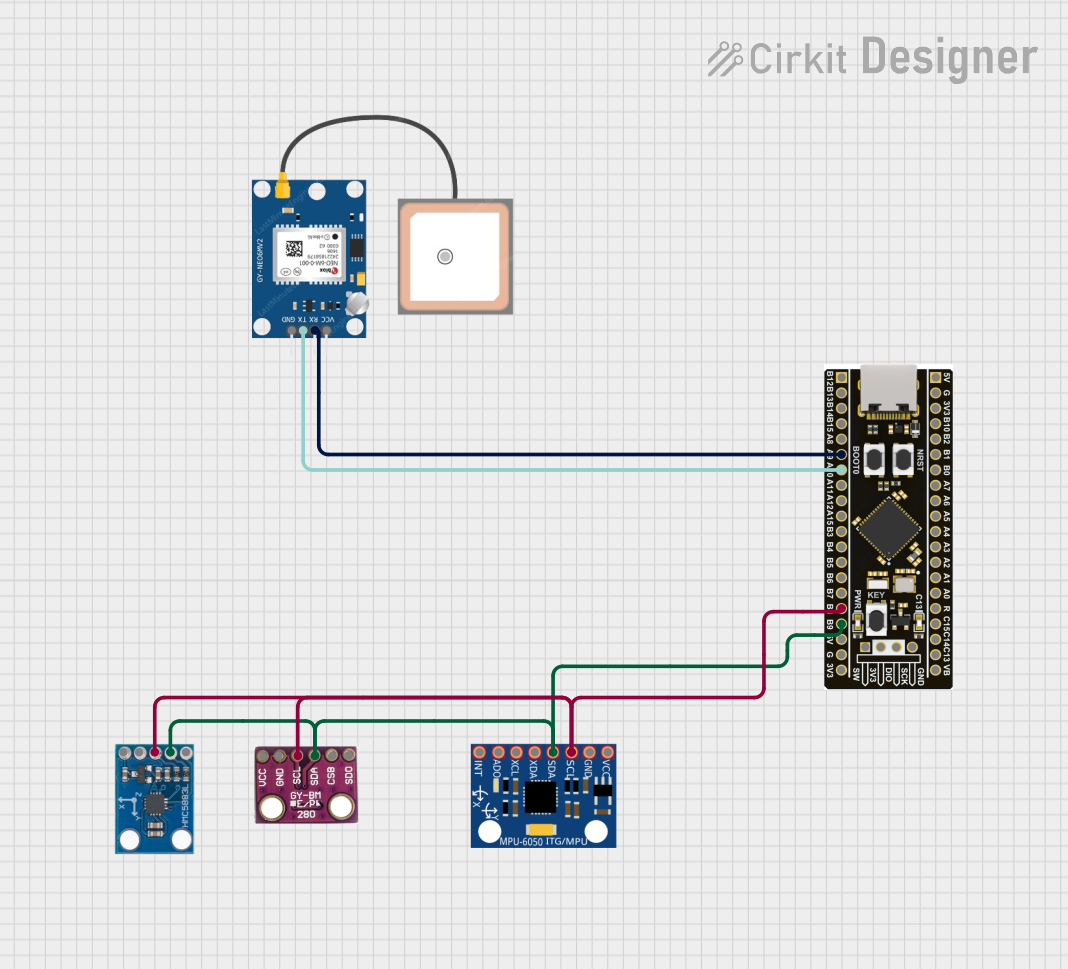 Open Project in Cirkit Designer
Explore Projects Built with GPS NEO-M8N
Open Project in Cirkit DesignerOpen Project in Cirkit DesignerOpen Project in Cirkit DesignerOpen Project in Cirkit DesignerTechnical Specifications
Below are the key technical details of the GPS NEO-M8N module:
| Parameter | Specification |
|---|---|
| GNSS Supported | GPS, GLONASS, Galileo, BeiDou |
| Position Accuracy | 2.5 meters (CEP) |
| Velocity Accuracy | 0.05 m/s |
| Time Accuracy | ±30 ns |
| Update Rate | Up to 10 Hz |
| Sensitivity | -167 dBm (tracking), -148 dBm (cold start) |
| Cold Start Time | 26 seconds |
| Hot Start Time | 1 second |
| Operating Voltage | 2.7V to 3.6V |
| Power Consumption | ~45 mA (continuous tracking mode) |
| Communication Interface | UART, I2C, SPI |
| Operating Temperature | -40°C to +85°C |
| Dimensions | 16 x 12.2 x 2.4 mm |
Pin Configuration and Descriptions
The GPS NEO-M8N module typically comes with the following pinout:
| Pin | Name | Description |
|---|---|---|
| 1 | VCC | Power supply input (2.7V to 3.6V). |
| 2 | GND | Ground connection. |
| 3 | TXD | UART Transmit pin (used to send data to a microcontroller or other devices). |
| 4 | RXD | UART Receive pin (used to receive data from a microcontroller or other devices). |
| 5 | SDA | I2C Data line (optional, for I2C communication). |
| 6 | SCL | I2C Clock line (optional, for I2C communication). |
| 7 | PPS | Pulse Per Second output for precise timing applications. |
| 8 | RESET | Reset pin (active low, used to reset the module). |
Usage Instructions
How to Use the GPS NEO-M8N in a Circuit
- Power Supply: Connect the VCC pin to a 3.3V power source and the GND pin to ground.
- Communication Interface:
- For UART communication, connect the TXD pin to the RX pin of your microcontroller and the RXD pin to the TX pin of your microcontroller.
- For I2C communication, connect the SDA and SCL pins to the corresponding I2C pins on your microcontroller.
- Antenna: Attach an active GPS antenna to the module's antenna connector for optimal signal reception.
- PPS Pin: If precise timing is required, connect the PPS pin to your microcontroller or timing circuit.
- Reset: Optionally, connect the RESET pin to a GPIO pin on your microcontroller for manual or software-controlled resets.
Important Considerations and Best Practices
- Antenna Placement: Ensure the GPS antenna has a clear view of the sky for optimal satellite reception. Avoid placing it near metal objects or inside enclosures that block signals.
- Power Supply: Use a stable and noise-free power source to avoid interference with the GPS signal.
- Baud Rate: The default UART baud rate is 9600 bps. Configure your microcontroller to match this rate or adjust it using the u-blox configuration software.
- Configuration: Use the u-blox u-center software to configure advanced settings, such as GNSS selection, update rate, and power-saving modes.
Example Code for Arduino UNO
Below is an example of how to interface the GPS NEO-M8N with an Arduino UNO using UART communication:
#include <SoftwareSerial.h>

// Define RX and TX pins for SoftwareSerial
SoftwareSerial gpsSerial(4, 3); // RX = Pin 4, TX = Pin 3

void setup() {
  Serial.begin(9600);          // Initialize Serial Monitor at 9600 bps
  gpsSerial.begin(9600);       // Initialize GPS module at 9600 bps
  Serial.println("GPS NEO-M8N Test");
}

void loop() {
  // Check if data is available from the GPS module
  while (gpsSerial.available()) {
    char c = gpsSerial.read(); // Read one character from GPS
    Serial.print(c);           // Print the character to Serial Monitor
  }
}
Note: Connect the GPS module's TXD pin to Arduino's Pin 4 and RXD pin to Arduino's Pin 3. Use a logic level shifter if your GPS module operates at 3.3V and your Arduino operates at 5V.
Troubleshooting and FAQs
Common Issues and Solutions
No GPS Fix:
- Ensure the antenna has a clear view of the sky.
- Wait for a few minutes, as the first fix (cold start) can take up to 26 seconds or longer in poor conditions.
- Check the power supply for stability and proper voltage.
No Data Output:
- Verify the UART connections (TXD and RXD) between the GPS module and the microcontroller.
- Ensure the baud rate of the GPS module matches the microcontroller's configuration.
- Check if the GPS module is powered on and functioning.
Inaccurate Positioning:
- Ensure the antenna is placed away from sources of interference, such as Wi-Fi routers or high-power electronics.
- Use an active antenna for better signal reception.
Module Not Responding:
- Reset the module using the RESET pin.
- Verify the wiring and ensure all connections are secure.
FAQs
Q: Can the GPS NEO-M8N work indoors?
A: The module may work indoors near windows, but signal reception is significantly reduced. For reliable operation, use it outdoors with a clear view of the sky.
Q: How many satellites does the module track simultaneously?
A: The NEO-M8N can track up to 72 channels simultaneously, depending on the GNSS configuration.
Q: Can I use the module with a 5V microcontroller?
A: Yes, but you must use a logic level shifter to safely interface the 3.3V GPS module with the 5V microcontroller.
Q: How do I change the update rate?
A: Use the u-blox u-center software to configure the update rate, which can go up to 10 Hz.
By following this documentation, you can effectively integrate the GPS NEO-M8N module into your projects and troubleshoot common issues.