How to Use Gearmotor DC Wheels Right: Examples, Pinouts, and Specs
Introduction
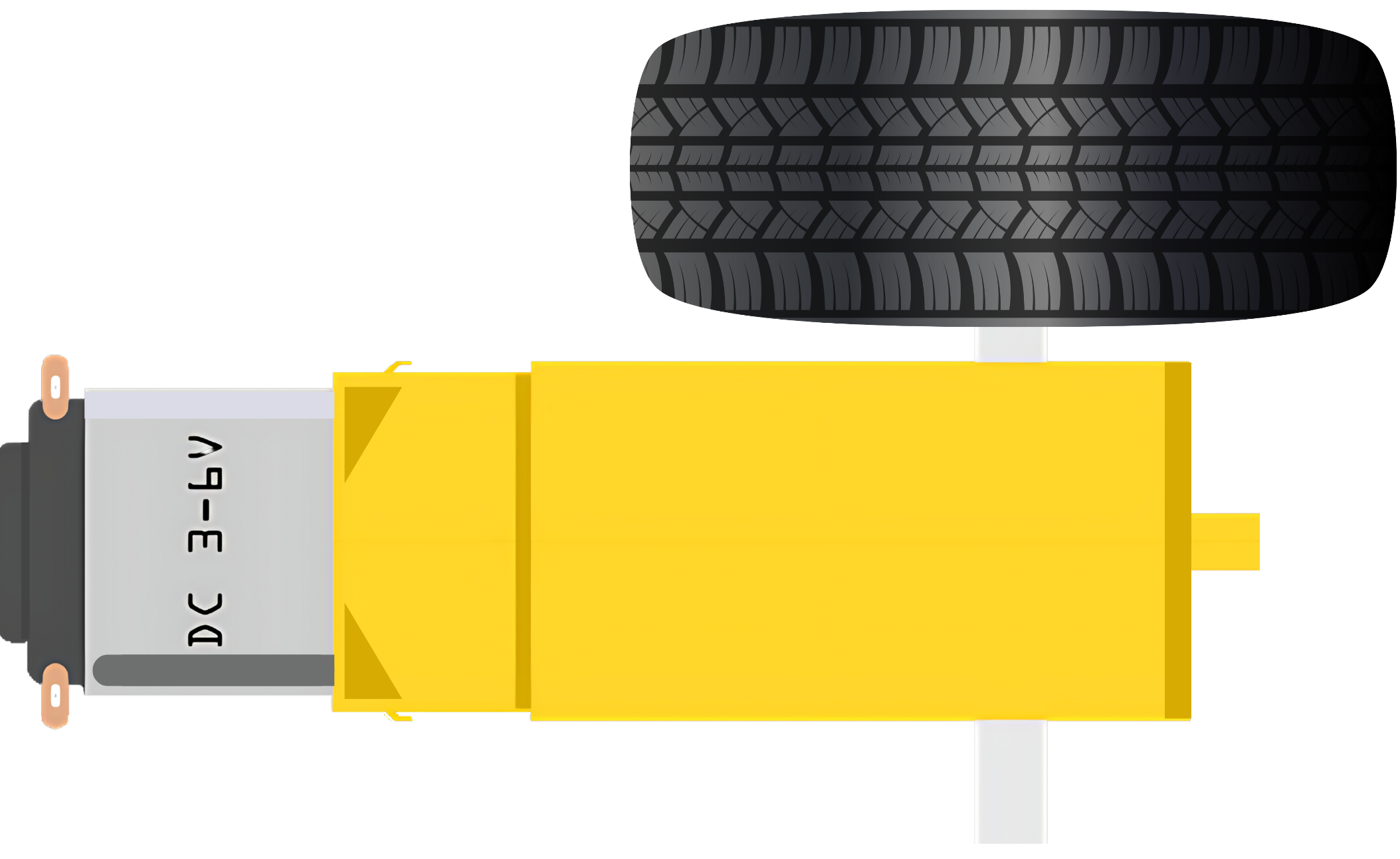
The Gearmotor Wheels Right is a geared DC motor with an attached wheel designed specifically for the right side of mobile robots or devices. This component is essential for providing motion and directional control, allowing the robot to move forward, backward, and turn. Common applications include hobbyist robotics projects, educational platforms, and prototyping for mobile devices.
Explore Projects Built with Gearmotor DC Wheels Right
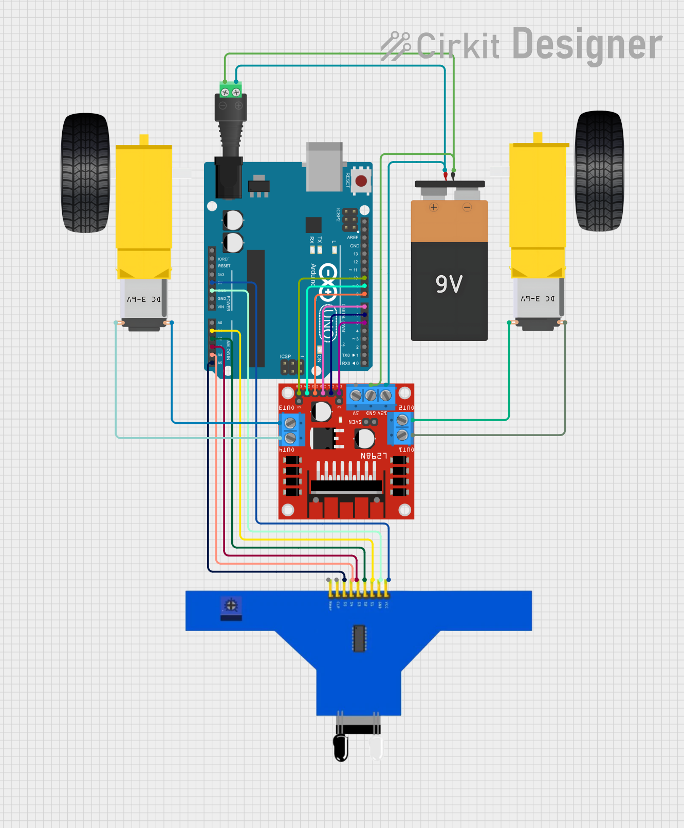

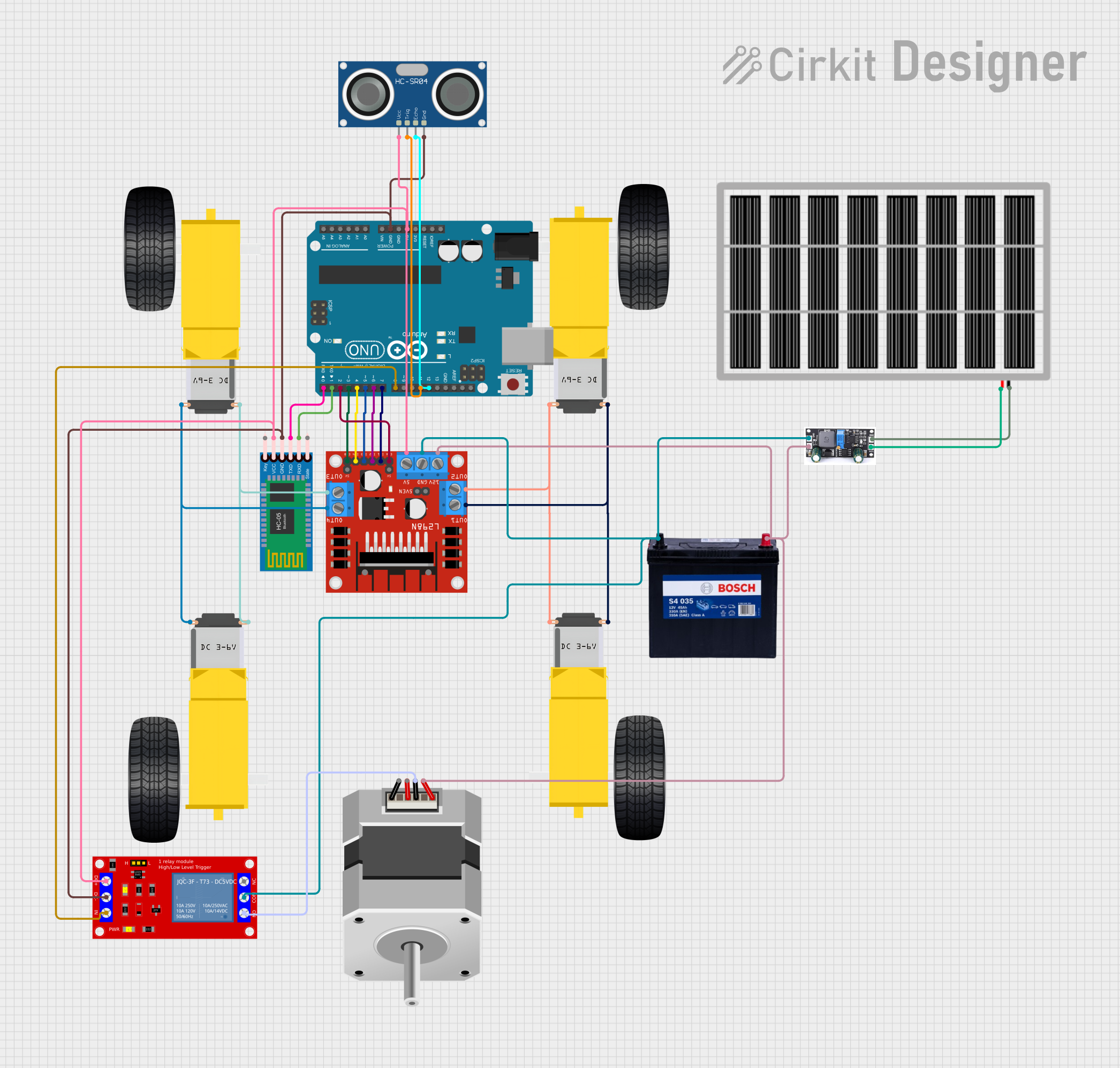
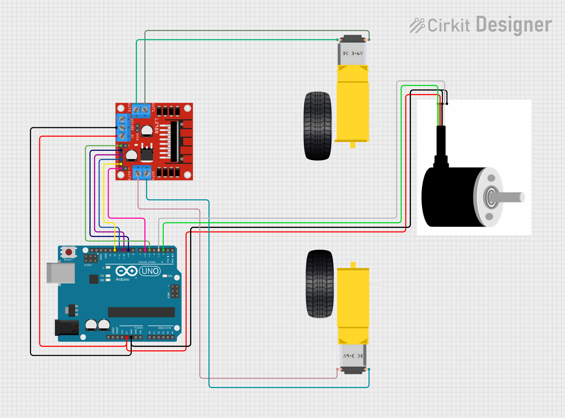
Explore Projects Built with Gearmotor DC Wheels Right
Technical Specifications
General Specifications
| Parameter | Value |
|---|---|
| Operating Voltage | 3V to 12V DC |
| Gear Ratio | Typically 48:1 to 120:1 |
| No-load Speed | 90 to 200 RPM (at 6V) |
| Stall Torque | 0.5 to 2 kg-cm (at 6V) |
| Wheel Diameter | 65 mm |
| Motor Type | Brushed DC Motor |
Pin Configuration and Descriptions
| Pin Number | Description |
|---|---|
| 1 | Motor Power (+) |
| 2 | Motor Power (-) |
Usage Instructions
Integration with a Circuit
To use the Gearmotor Wheels Right in a circuit:
- Connect the motor power pins to a motor driver or H-bridge circuit. The motor driver should be capable of handling the motor's voltage and current requirements.
- Ensure that the motor driver is connected to a power supply that matches the motor's operating voltage.
- Connect the control inputs of the motor driver to the output pins of a microcontroller, such as an Arduino UNO, to control the speed and direction of the motor.
Best Practices
- Use a motor driver with overcurrent protection to prevent damage to the motor.
- Avoid stalling the motor for extended periods, as this can lead to overheating and damage.
- When mounting the motor, ensure that the wheel is free to rotate and is not obstructed.
- Regularly check the wheel attachment to the motor shaft for any signs of wear or loosening.
Example Code for Arduino UNO
#include <Arduino.h>

// Define motor control pins
const int motorPin1 = 3; // Motor control pin 1
const int motorPin2 = 4; // Motor control pin 2

void setup() {
  // Set motor control pins as outputs
  pinMode(motorPin1, OUTPUT);
  pinMode(motorPin2, OUTPUT);
}

void loop() {
  // Rotate the motor clockwise
  digitalWrite(motorPin1, HIGH);
  digitalWrite(motorPin2, LOW);
  delay(1000); // Run for 1 second

  // Stop the motor
  digitalWrite(motorPin1, LOW);
  digitalWrite(motorPin2, LOW);
  delay(1000); // Stop for 1 second

  // Rotate the motor counterclockwise
  digitalWrite(motorPin1, LOW);
  digitalWrite(motorPin2, HIGH);
  delay(1000); // Run for 1 second

  // Repeat the cycle
}
Troubleshooting and FAQs
Common Issues
- Motor does not turn: Check connections to the motor driver and power supply. Ensure the motor driver is functioning correctly and the power supply voltage is within the specified range.
- Motor turns slowly or lacks torque: Verify that the power supply can deliver sufficient current. Check for any obstructions that may be hindering wheel movement.
- Motor overheats: Ensure that the motor is not stalled and that the operating voltage is not exceeding the recommended range.
FAQs
Q: Can I run the motor directly from an Arduino pin? A: No, the Arduino pins cannot supply enough current for the motor. Use a motor driver to control the motor.
Q: What is the maximum voltage I can apply to the motor? A: The maximum recommended voltage is 12V DC. Exceeding this voltage may damage the motor.
Q: How do I reverse the direction of the motor? A: To reverse the direction, reverse the polarity of the motor power connections. This can be done using an H-bridge or motor driver.
Q: Can I use PWM to control the speed of the motor? A: Yes, you can use PWM on the control inputs of the motor driver to vary the speed of the motor.
Q: How do I attach the wheel to the motor shaft? A: The wheel typically comes with a set screw that can be tightened onto the flat side of the motor shaft. Ensure it is secure before operation.