How to Use Motor Driver: Examples, Pinouts, and Specs
Introduction
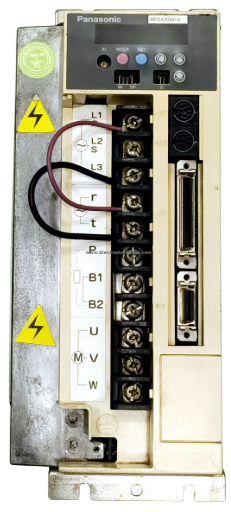
The Panasonic MDD100 is a high-performance motor driver designed to control the operation of DC motors, stepper motors, or servo motors. It acts as an interface between a microcontroller and the motor, enabling precise control of speed, direction, and torque. The MDD100 is ideal for applications requiring efficient motor control, such as robotics, industrial automation, and consumer electronics.
Explore Projects Built with Motor Driver

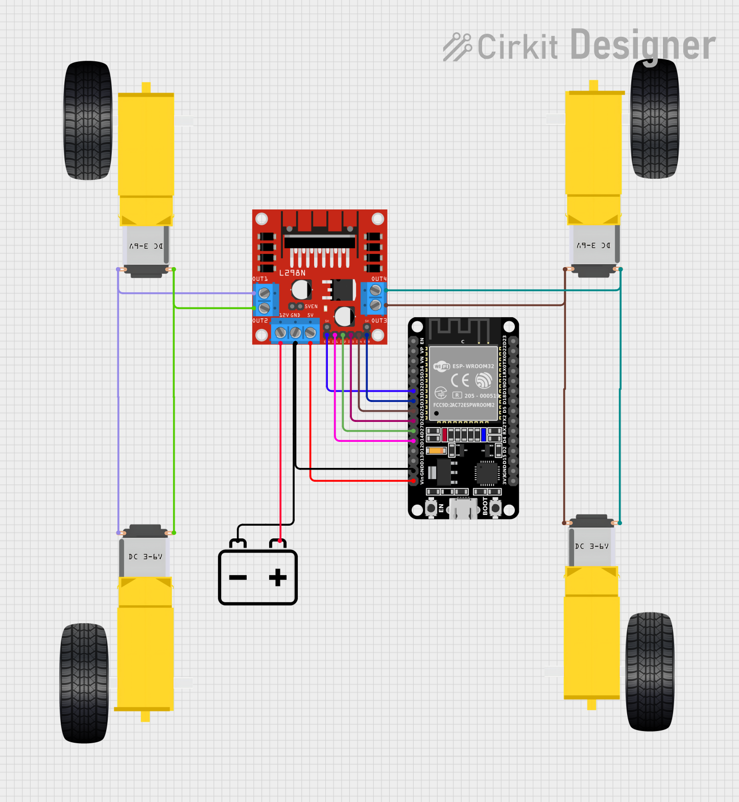


Explore Projects Built with Motor Driver
Common Applications
- Robotics and automation systems
- Conveyor belts and industrial machinery
- Electric vehicles and drones
- Home appliances (e.g., fans, washing machines)
- Precision control systems for stepper or servo motors
Technical Specifications
Key Technical Details
| Parameter | Value |
|---|---|
| Manufacturer | Panasonic |
| Part Number | MDD100 |
| Operating Voltage Range | 6V to 36V |
| Maximum Output Current | 2A per channel (continuous) |
| Peak Output Current | 3A per channel (short duration) |
| Number of Channels | 2 (dual H-bridge configuration) |
| Control Logic Voltage | 3.3V or 5V |
| PWM Frequency | Up to 20 kHz |
| Operating Temperature | -20°C to 85°C |
| Package Type | DIP-16 or SOIC-16 |
Pin Configuration and Descriptions
The MDD100 features a 16-pin configuration. Below is the pinout and description:
| Pin Number | Pin Name | Description |
|---|---|---|
| 1 | VCC | Motor power supply (6V to 36V). |
| 2 | GND | Ground connection. |
| 3 | IN1 | Input signal for controlling Motor 1 direction. |
| 4 | IN2 | Input signal for controlling Motor 1 direction. |
| 5 | ENA | Enable pin for Motor 1 (PWM input for speed control). |
| 6 | OUT1 | Output pin for Motor 1 connection. |
| 7 | OUT2 | Output pin for Motor 1 connection. |
| 8 | NC | Not connected. |
| 9 | OUT3 | Output pin for Motor 2 connection. |
| 10 | OUT4 | Output pin for Motor 2 connection. |
| 11 | ENB | Enable pin for Motor 2 (PWM input for speed control). |
| 12 | IN3 | Input signal for controlling Motor 2 direction. |
| 13 | IN4 | Input signal for controlling Motor 2 direction. |
| 14 | GND | Ground connection. |
| 15 | VCC | Motor power supply (6V to 36V). |
| 16 | NC | Not connected. |
Usage Instructions
How to Use the MDD100 in a Circuit
- Power Supply: Connect the motor power supply (6V to 36V) to the
VCCpin and ground to theGNDpin. Ensure the power supply matches the motor's voltage requirements. - Motor Connections: Connect the motor terminals to the
OUT1andOUT2pins for Motor 1, andOUT3andOUT4pins for Motor 2. - Control Signals: Use the
IN1,IN2,IN3, andIN4pins to control the direction of the motors. Apply a PWM signal to theENAandENBpins to control motor speed. - Logic Voltage: Ensure the control logic voltage (3.3V or 5V) is compatible with your microcontroller.
- Heat Dissipation: If operating at high currents, consider adding a heat sink to the MDD100 to prevent overheating.
Example: Connecting to an Arduino UNO
Below is an example of how to control a DC motor using the MDD100 and an Arduino UNO:
Circuit Connections
- Connect
VCCto a 12V power supply andGNDto ground. - Connect Motor 1 terminals to
OUT1andOUT2. - Connect
ENAto Arduino pin 9 (PWM output). - Connect
IN1andIN2to Arduino pins 7 and 8, respectively.
Arduino Code
// Define motor control pins
const int ENA = 9;  // PWM pin for speed control
const int IN1 = 7;  // Direction control pin 1
const int IN2 = 8;  // Direction control pin 2

void setup() {
  // Set motor control pins as outputs
  pinMode(ENA, OUTPUT);
  pinMode(IN1, OUTPUT);
  pinMode(IN2, OUTPUT);
}

void loop() {
  // Rotate motor forward
  digitalWrite(IN1, HIGH);  // Set IN1 high
  digitalWrite(IN2, LOW);   // Set IN2 low
  analogWrite(ENA, 128);    // Set speed to 50% (PWM value: 128)

  delay(2000);  // Run motor for 2 seconds

  // Stop motor
  digitalWrite(IN1, LOW);   // Set IN1 low
  digitalWrite(IN2, LOW);   // Set IN2 low
  analogWrite(ENA, 0);      // Set speed to 0

  delay(1000);  // Wait for 1 second

  // Rotate motor backward
  digitalWrite(IN1, LOW);   // Set IN1 low
  digitalWrite(IN2, HIGH);  // Set IN2 high
  analogWrite(ENA, 128);    // Set speed to 50% (PWM value: 128)

  delay(2000);  // Run motor for 2 seconds

  // Stop motor
  digitalWrite(IN1, LOW);   // Set IN1 low
  digitalWrite(IN2, LOW);   // Set IN2 low
  analogWrite(ENA, 0);      // Set speed to 0

  delay(1000);  // Wait for 1 second
}
Important Considerations
- Ensure the motor's current and voltage ratings are within the MDD100's specifications.
- Use decoupling capacitors near the
VCCpin to reduce noise and voltage spikes. - Avoid short circuits between the output pins, as this may damage the driver.
Troubleshooting and FAQs
Common Issues and Solutions
Motor Not Spinning:
- Verify the power supply connection to the
VCCandGNDpins. - Check the control signals (
IN1,IN2,ENA) for proper logic levels. - Ensure the motor is connected to the correct output pins (
OUT1,OUT2).
- Verify the power supply connection to the
Motor Spins in the Wrong Direction:
- Reverse the logic levels on the direction control pins (
IN1andIN2). - Swap the motor terminals connected to the output pins.
- Reverse the logic levels on the direction control pins (
Overheating:
- Ensure the current drawn by the motor does not exceed the MDD100's maximum rating.
- Add a heat sink or improve ventilation around the driver.
PWM Signal Not Working:
- Verify the PWM frequency is within the supported range (up to 20 kHz).
- Check the microcontroller's PWM pin configuration.
FAQs
Q: Can the MDD100 drive two motors simultaneously?
A: Yes, the MDD100 has a dual H-bridge configuration, allowing it to control two motors independently.
Q: Is the MDD100 compatible with 3.3V logic?
A: Yes, the MDD100 supports both 3.3V and 5V logic levels for control signals.
Q: What type of motors can the MDD100 drive?
A: The MDD100 can drive DC motors, stepper motors, and servo motors within its voltage and current ratings.
Q: Do I need external diodes for motor protection?
A: No, the MDD100 includes built-in flyback diodes for motor protection.