How to Use LM5574: Examples, Pinouts, and Specs
Introduction
The LM5574 is a highly efficient, switch mode buck (step-down) regulator designed to convert a higher input voltage to a lower output voltage. Its versatility and robustness make it suitable for a wide range of applications, including but not limited to, industrial power systems, automotive electronics, and distributed power systems. The LM5574 is known for its power efficiency and compact size, which are critical in applications where space and energy consumption are of concern.
Explore Projects Built with LM5574

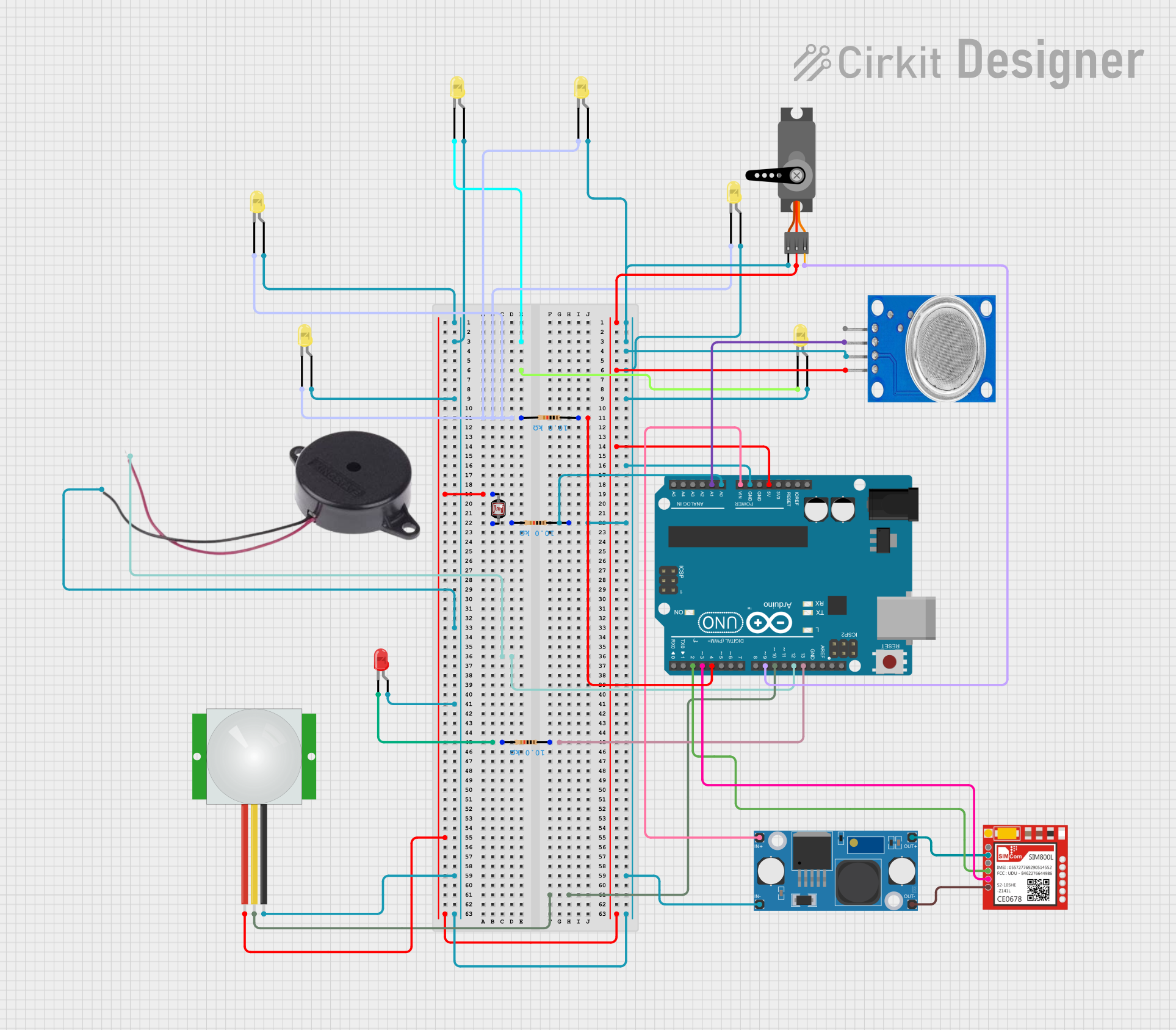
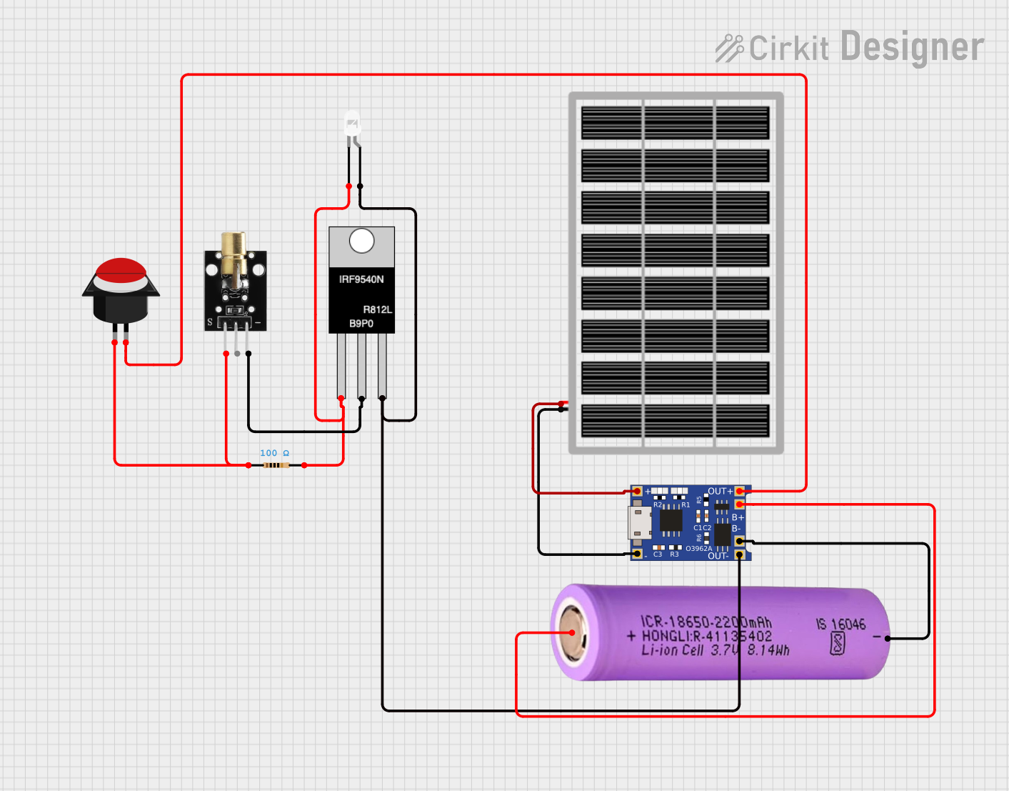

Explore Projects Built with LM5574
Technical Specifications
Key Technical Details
- Input Voltage Range: 6V to 75V
- Output Voltage Range: 1.225V to 55V (adjustable)
- Output Current: Up to 0.75A
- Switching Frequency: 50kHz to 500kHz (adjustable)
- Efficiency: Up to 95% (dependent on input/output conditions)
- Operating Temperature Range: -40°C to 125°C
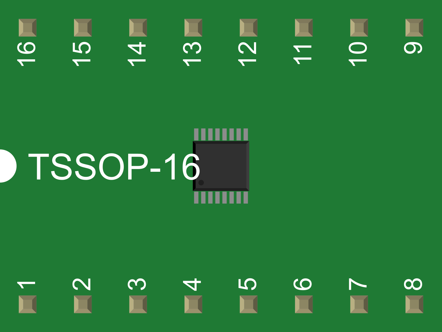
Pin Configuration and Descriptions
| Pin Number | Name | Description |
|---|---|---|
| 1 | VIN | Input voltage to the regulator. Connect to the source voltage. |
| 2 | GND | Ground reference for the regulator. |
| 3 | SW | Switch node. Connect to the inductor and diode. |
| 4 | FB | Feedback pin. Connect to the output voltage divider to set the output voltage. |
| 5 | COMP | Compensation pin. Connect to the external compensation network. |
| 6 | RT/SYNC | Timing resistor or synchronization pin. Set the switching frequency or synchronize to an external clock. |
| 7 | ON/OFF | Enable pin. Drive high to turn on the regulator, low to turn it off. |
| 8 | VCC | Internal regulator output. Provides bias voltage for the internal circuitry. |
Usage Instructions
How to Use the LM5574 in a Circuit
- Input Supply: Connect a voltage source within the specified input voltage range to the VIN pin (Pin 1) and ground to the GND pin (Pin 2).
- Output Voltage Setting: Use a voltage divider from the output to the FB pin (Pin 4) to set the desired output voltage.
- Switch Node: Connect an inductor between the SW pin (Pin 3) and the output load. Also, connect a catch diode from the SW pin to ground.
- Frequency Setting: Place a resistor on the RT/SYNC pin (Pin 6) to set the switching frequency, or connect an external clock for synchronization.
- Compensation Network: Attach a compensation network to the COMP pin (Pin 5) to ensure stability.
- Enable/Disable: Control the ON/OFF pin (Pin 7) with a logic signal to enable or disable the regulator.
- VCC Pin: The VCC pin (Pin 8) should be decoupled with a capacitor to ground.
Important Considerations and Best Practices
- Ensure that all components, especially the inductor and diode, are rated for the current and voltage requirements of your application.
- Place decoupling capacitors close to the VIN and VCC pins to minimize noise and voltage spikes.
- Keep the switching node (SW) trace as short as possible to reduce EMI and losses.
- Use a proper heat sink or thermal management techniques if the regulator is expected to dissipate significant power.
- Follow the manufacturer's layout guidelines for optimal performance and stability.
Troubleshooting and FAQs
Common Issues
- Output Voltage is Incorrect: Check the feedback voltage divider values and ensure they are within tolerance.
- Regulator Overheating: Verify that the power dissipation is within the limits and improve heat sinking if necessary.
- Excessive Noise or Ripple: Ensure proper layout and decoupling, and check if the compensation network is correctly designed.
Solutions and Tips for Troubleshooting
- Incorrect Output Voltage: Recalculate the feedback resistor values and replace them if necessary.
- Overheating: Reduce the load current, improve airflow, or use a larger heat sink.
- Noise or Ripple: Use low ESR capacitors for input and output decoupling and review the PCB layout.
FAQs
Q: Can the LM5574 be synchronized to an external clock? A: Yes, the LM5574 can be synchronized by applying an external clock signal to the RT/SYNC pin.
Q: What is the maximum output current of the LM5574? A: The LM5574 can deliver up to 0.75A of output current.
Q: How do I adjust the switching frequency of the LM5574? A: The switching frequency can be adjusted by changing the resistor value connected to the RT/SYNC pin or by synchronizing to an external clock.
Example Code for Arduino UNO
Below is an example code snippet for controlling the ON/OFF pin of the LM5574 using an Arduino UNO. This code will enable the LM5574 for 5 seconds and then disable it for 5 seconds in a loop.
const int enablePin = 7; // Connect to the ON/OFF pin of LM5574

void setup() {
  pinMode(enablePin, OUTPUT);
}

void loop() {
  digitalWrite(enablePin, HIGH); // Enable the LM5574
  delay(5000);                   // Wait for 5 seconds
  digitalWrite(enablePin, LOW);  // Disable the LM5574
  delay(5000);                   // Wait for 5 seconds
}
Remember to adjust the enablePin to match the actual pin on the Arduino UNO that is connected to the LM5574's ON/OFF pin.