How to Use IR Emitter: Examples, Pinouts, and Specs
Introduction
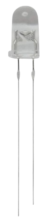
An IR Emitter is a device that emits infrared (IR) light, which is invisible to the human eye but can be detected by IR receivers. It is commonly used in remote controls, wireless communication systems, and proximity sensors. IR Emitters are essential components in applications where wireless data transmission or object detection is required.
Explore Projects Built with IR Emitter

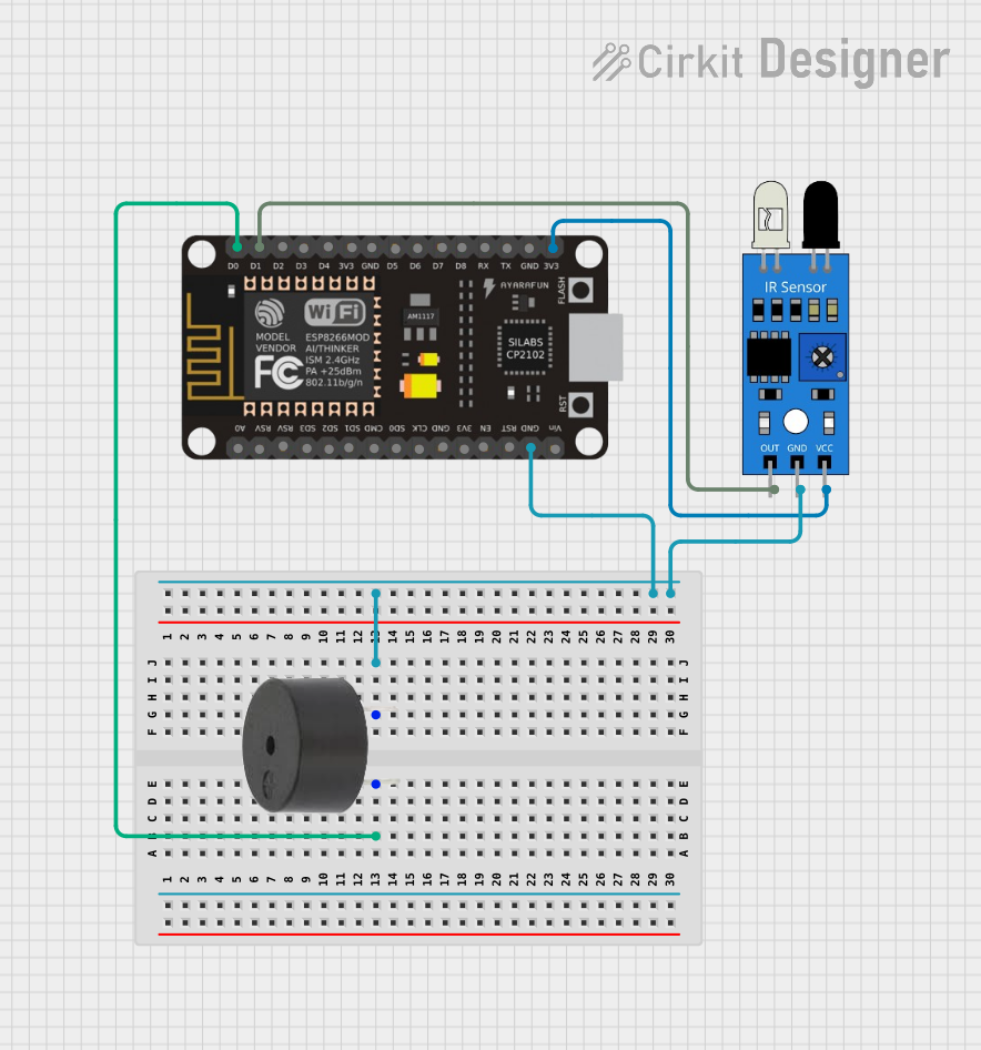
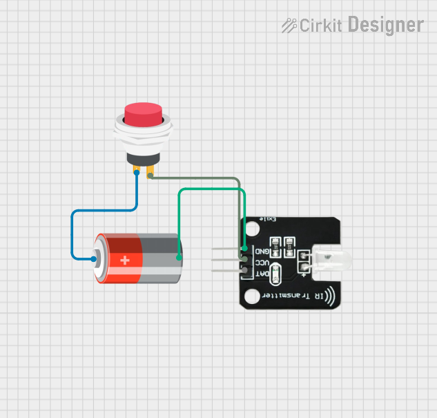
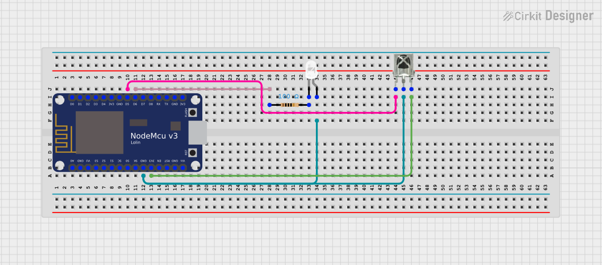
Explore Projects Built with IR Emitter
Common Applications and Use Cases
- Remote controls for TVs, air conditioners, and other appliances
- Wireless communication between devices
- Proximity and motion detection systems
- Infrared data transmission in robotics
- Security systems and surveillance
Technical Specifications
Below are the general technical specifications for a standard IR Emitter. Note that specific values may vary depending on the manufacturer and model.
| Parameter | Value |
|---|---|
| Wavelength | 850 nm to 950 nm |
| Forward Voltage (Vf) | 1.2V to 1.5V |
| Forward Current (If) | 20 mA (typical), 50 mA (max) |
| Power Dissipation | 100 mW (max) |
| Viewing Angle | 20° to 60° |
| Package Type | Through-hole or SMD |
Pin Configuration and Descriptions
| Pin Name | Description |
|---|---|
| Anode (+) | Positive terminal; connect to power supply |
| Cathode (-) | Negative terminal; connect to ground |
Usage Instructions
How to Use the IR Emitter in a Circuit
Determine the Resistor Value: To prevent damage to the IR Emitter, calculate the appropriate current-limiting resistor using Ohm's Law: [ R = \frac{V_{supply} - V_f}{I_f} ] Where:
- ( V_{supply} ) is the supply voltage
- ( V_f ) is the forward voltage of the IR Emitter
- ( I_f ) is the desired forward current (e.g., 20 mA)
Connect the IR Emitter:
- Connect the anode (+) to the positive terminal of the power supply through the current-limiting resistor.
- Connect the cathode (-) to the ground.
Test the Circuit: Use an IR receiver or a camera (e.g., a smartphone camera) to verify that the IR Emitter is functioning. The camera can detect the IR light as a faint glow.
Important Considerations and Best Practices
- Current Limiting: Always use a resistor to limit the current through the IR Emitter to avoid overheating or damage.
- Viewing Angle: Ensure the IR Emitter is aligned with the IR receiver for optimal signal transmission.
- Power Supply: Use a stable power supply to maintain consistent performance.
- Heat Dissipation: Avoid exceeding the maximum power dissipation to prevent thermal damage.
Example: Using an IR Emitter with Arduino UNO
Below is an example of how to control an IR Emitter using an Arduino UNO:
// Example: Blink an IR Emitter using Arduino UNO
// Connect the anode of the IR Emitter to pin 3 (via a resistor) and the cathode to GND.

const int irEmitterPin = 3; // IR Emitter connected to digital pin 3

void setup() {
  pinMode(irEmitterPin, OUTPUT); // Set the IR Emitter pin as an output
}

void loop() {
  digitalWrite(irEmitterPin, HIGH); // Turn the IR Emitter ON
  delay(500); // Wait for 500 milliseconds
  digitalWrite(irEmitterPin, LOW); // Turn the IR Emitter OFF
  delay(500); // Wait for 500 milliseconds
}
Troubleshooting and FAQs
Common Issues and Solutions
IR Emitter Not Working:
- Cause: Incorrect resistor value or no resistor used.
- Solution: Recalculate the resistor value and ensure it is connected in series with the IR Emitter.
Weak or No Signal Detected:
- Cause: Misalignment between the IR Emitter and receiver.
- Solution: Adjust the position and angle of the IR Emitter to align with the receiver.
Overheating:
- Cause: Excessive current through the IR Emitter.
- Solution: Verify the resistor value and ensure it limits the current to the recommended range.
IR Light Not Visible:
- Cause: IR light is invisible to the human eye.
- Solution: Use a camera or IR receiver to confirm the IR Emitter is functioning.
FAQs
Q: Can I use an IR Emitter without a resistor?
A: No, using an IR Emitter without a resistor can result in excessive current flow, leading to overheating and permanent damage.
Q: How do I increase the range of the IR Emitter?
A: Use a higher current (within the maximum rating) and ensure proper alignment with the receiver. You can also use a lens to focus the IR beam.
Q: Can I use an IR Emitter with a 3.3V power supply?
A: Yes, as long as you calculate the appropriate resistor value for the 3.3V supply and ensure the forward current does not exceed the maximum rating.
Q: How do I know if the IR Emitter is working?
A: Use a smartphone camera or an IR receiver module to detect the emitted IR light.