How to Use STM32F103C8T6 System Board (Blue Pill) STM32 ARM Core Board (Original) - ChipTronicX: Examples, Pinouts, and Specs
Introduction
The STM32F103C8T6 System Board, commonly referred to as the "Blue Pill," is a compact and versatile development board based on the STM32F103C8T6 microcontroller. This microcontroller is part of the ARM Cortex-M3 family, offering a balance of performance, power efficiency, and affordability. The Blue Pill is widely used in embedded systems, IoT projects, robotics, and other applications requiring real-time processing and control.
Explore Projects Built with STM32F103C8T6 System Board (Blue Pill) STM32 ARM Core Board (Original) - ChipTronicX


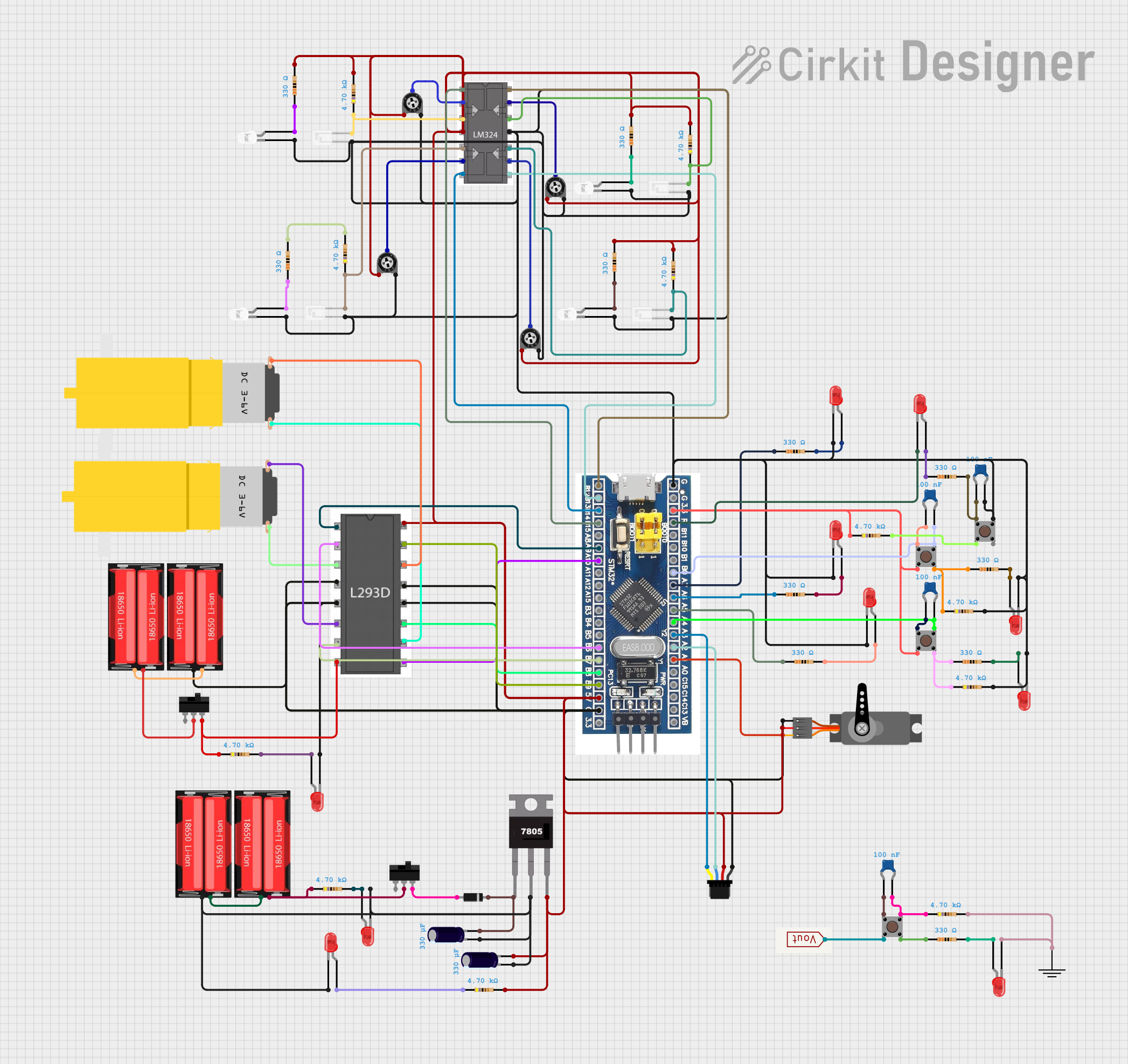
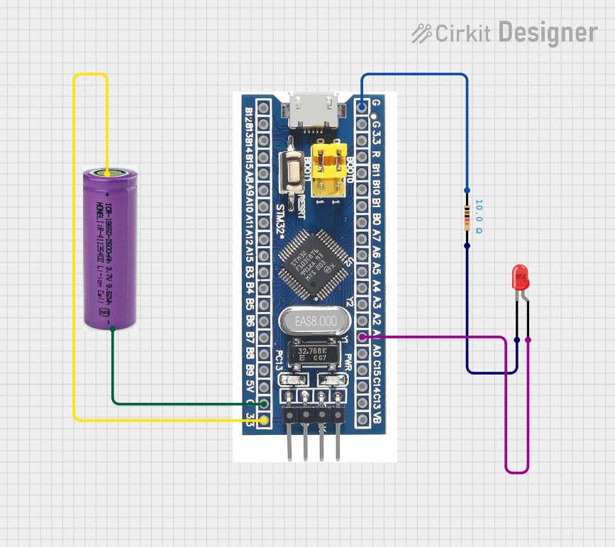
Explore Projects Built with STM32F103C8T6 System Board (Blue Pill) STM32 ARM Core Board (Original) - ChipTronicX
Common Applications and Use Cases
- IoT devices and smart home automation
- Robotics and motor control
- Data acquisition and sensor interfacing
- Prototyping and educational purposes
- Low-power embedded systems
Technical Specifications
Key Technical Details
| Specification | Value |
|---|---|
| Microcontroller | STM32F103C8T6 (ARM Cortex-M3) |
| Operating Voltage | 3.3V |
| Input Voltage Range | 5V (via USB) or 7-12V (via VIN) |
| Flash Memory | 64 KB |
| SRAM | 20 KB |
| Clock Speed | 72 MHz |
| GPIO Pins | 37 |
| Communication Interfaces | UART, SPI, I2C, CAN, USB |
| ADC Resolution | 12-bit (10 channels) |
| PWM Channels | 15 |
| Dimensions | 53 mm x 22 mm |
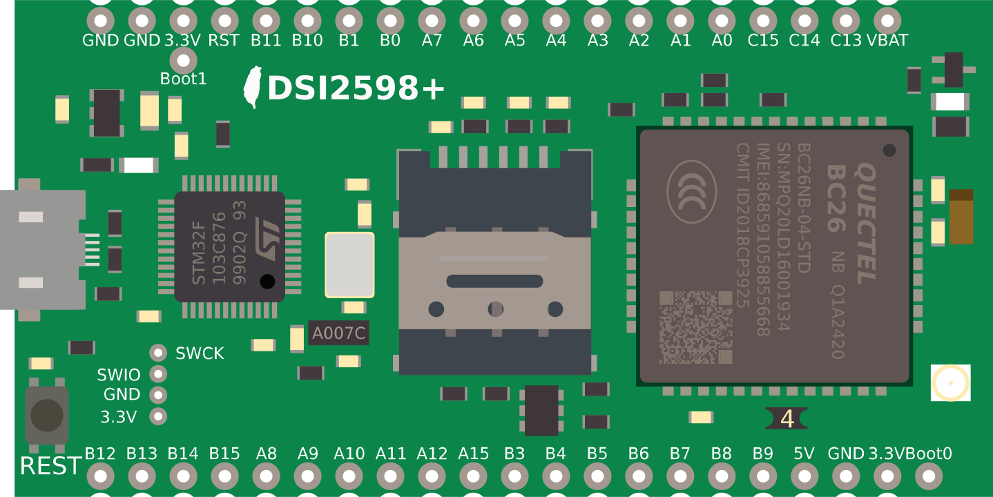
Pin Configuration and Descriptions
The STM32F103C8T6 System Board features two rows of 20 pins each. Below is a summary of the pin configuration:
| Pin Number | Label | Description |
|---|---|---|
| 1 | GND | Ground |
| 2 | 3.3V | 3.3V Power Output |
| 3 | 5V | 5V Power Input |
| 4 | PA0 - PA15 | General Purpose I/O (GPIO) Pins |
| 5 | PB0 - PB15 | General Purpose I/O (GPIO) Pins |
| 6 | PC13 - PC15 | General Purpose I/O (GPIO) Pins |
| 7 | NRST | Reset Pin |
| 8 | BOOT0 | Boot Mode Selection |
| 9 | USB+ / USB- | USB Data Lines |
| 10 | TX / RX | UART Communication Pins |
For a complete pinout diagram, refer to the official datasheet or schematic.
Usage Instructions
How to Use the Component in a Circuit
Powering the Board:
- Connect the board to a 5V USB power source or supply 7-12V to the VIN pin.
- Ensure the BOOT0 pin is set to the correct mode (default is 0 for normal operation).
Programming the Board:
- Use a USB-to-Serial adapter or ST-Link programmer to upload code.
- Install the STM32CubeIDE or Arduino IDE with the STM32 core for development.
- Select the correct board and port in your IDE.
Connecting Peripherals:
- Use GPIO pins for digital input/output.
- Connect sensors to ADC pins for analog input.
- Use UART, SPI, or I2C for communication with other devices.
Important Considerations and Best Practices
- Voltage Levels: The GPIO pins operate at 3.3V. Avoid applying 5V directly to these pins to prevent damage.
- Boot Modes: Set the BOOT0 pin to 1 for flashing firmware and back to 0 for normal operation.
- Decoupling Capacitors: Add decoupling capacitors near the power pins to ensure stable operation.
- Clock Configuration: Use an external 8 MHz crystal oscillator for accurate timing.
Example Code for Arduino IDE
Below is an example of blinking an LED connected to pin PC13:
// Include the STM32 core library
#include <Arduino.h>

// Define the LED pin (PC13 is onboard LED on Blue Pill)
#define LED_PIN PC13

void setup() {
  pinMode(LED_PIN, OUTPUT); // Set PC13 as an output pin
}

void loop() {
  digitalWrite(LED_PIN, HIGH); // Turn the LED on
  delay(500);                  // Wait for 500 milliseconds
  digitalWrite(LED_PIN, LOW);  // Turn the LED off
  delay(500);                  // Wait for 500 milliseconds
}
Troubleshooting and FAQs
Common Issues Users Might Face
Board Not Detected by IDE:
- Ensure the correct drivers are installed for the USB-to-Serial adapter or ST-Link.
- Verify that the BOOT0 pin is set to the correct mode.
Code Upload Fails:
- Check the connection between the board and the programmer.
- Ensure the correct board and port are selected in the IDE.
GPIO Pins Not Responding:
- Confirm that the pins are configured correctly in the code.
- Check for short circuits or incorrect wiring.
Board Overheating:
- Verify that the input voltage does not exceed the recommended range.
- Check for excessive current draw from connected peripherals.
Solutions and Tips for Troubleshooting
- Use a multimeter to check power supply voltages and continuity of connections.
- If the board is unresponsive, try resetting it using the NRST pin.
- For debugging, use the Serial Monitor in the IDE to print diagnostic messages.
By following this documentation, users can effectively utilize the STM32F103C8T6 System Board for a wide range of applications.