Cirkit Designer Logo
Cirkit Designer
Your all-in-one circuit design IDE
Home / 
Component Documentation

How to Use ESP32 WITH POWER PIN: Examples, Pinouts, and Specs

Image of ESP32 WITH POWER PIN
Cirkit Designer LogoDesign with ESP32 WITH POWER PIN in Cirkit Designer

Introduction

The ESP32 is a versatile and powerful microcontroller developed by ESP32, featuring integrated Wi-Fi and Bluetooth capabilities. It is widely used in Internet of Things (IoT) applications, smart devices, and wireless communication projects. The inclusion of a dedicated power pin simplifies the connection to a power source, ensuring reliable operation of the microcontroller.

Explore Projects Built with ESP32 WITH POWER PIN

Use Cirkit Designer to design, explore, and prototype these projects online. Some projects support real-time simulation. Click "Open Project" to start designing instantly!
ESP32-Controlled AC Lighting System with Power Monitoring
Image of Smart Energy Meter: A project utilizing ESP32 WITH POWER PIN in a practical application
This circuit features an ESP32 microcontroller interfaced with a PZEM004T power monitoring module and a 4-channel relay module controlling multiple AC LED bulbs. The ESP32 uses GPIO pins to control the relays, which in turn switch the LED bulbs on and off. The PZEM004T is connected to the ESP32 for communication and to a current sensor for monitoring power consumption of the connected load through the relay contacts.
Cirkit Designer LogoOpen Project in Cirkit Designer
ESP32-Based Portable NFC/RFID Reader with OLED Interface
Image of omnitool: A project utilizing ESP32 WITH POWER PIN in a practical application
This circuit features an ESP32 microcontroller connected to a 0.96" OLED display via I2C (SCK and SDA lines), multiple pushbuttons interfaced to various GPIO pins for input, and a LiPoly battery connected through a TP4056 charging/protection module to power the system. A step-up boost power converter adjusts the battery voltage to supply the ESP32 and OLED display. The toggle switch controls the power flow from the battery to the converter, enabling an on/off functionality for the circuit.
Cirkit Designer LogoOpen Project in Cirkit Designer
ESP32-Based Water Sensor with Wi-Fi Connectivity
Image of KALMAN: A project utilizing ESP32 WITH POWER PIN in a practical application
This circuit consists of an ESP32 microcontroller connected to a water sensor. The water sensor's signal pin is connected to the ESP32's D12 pin, while the power and ground pins are connected to the ESP32's 3.3V and GND pins, respectively. The circuit is designed to detect water presence and send the data to the ESP32 for further processing or communication.
Cirkit Designer LogoOpen Project in Cirkit Designer
ESP32 and Logic Level Converter-Based Wi-Fi Controlled Interface
Image of Toshiba AC ESP32 devkit v1: A project utilizing ESP32 WITH POWER PIN in a practical application
This circuit features an ESP32 Devkit V1 microcontroller connected to a Bi-Directional Logic Level Converter, which facilitates voltage level shifting between the ESP32 and external components. The ESP32 is powered through its VIN pin via an alligator clip cable, and the logic level converter is connected to various pins on the ESP32 to manage different voltage levels for communication.
Cirkit Designer LogoOpen Project in Cirkit Designer

Explore Projects Built with ESP32 WITH POWER PIN

Use Cirkit Designer to design, explore, and prototype these projects online. Some projects support real-time simulation. Click "Open Project" to start designing instantly!
Image of Smart Energy Meter: A project utilizing ESP32 WITH POWER PIN in a practical application
ESP32-Controlled AC Lighting System with Power Monitoring
This circuit features an ESP32 microcontroller interfaced with a PZEM004T power monitoring module and a 4-channel relay module controlling multiple AC LED bulbs. The ESP32 uses GPIO pins to control the relays, which in turn switch the LED bulbs on and off. The PZEM004T is connected to the ESP32 for communication and to a current sensor for monitoring power consumption of the connected load through the relay contacts.
Cirkit Designer LogoOpen Project in Cirkit Designer
Image of omnitool: A project utilizing ESP32 WITH POWER PIN in a practical application
ESP32-Based Portable NFC/RFID Reader with OLED Interface
This circuit features an ESP32 microcontroller connected to a 0.96" OLED display via I2C (SCK and SDA lines), multiple pushbuttons interfaced to various GPIO pins for input, and a LiPoly battery connected through a TP4056 charging/protection module to power the system. A step-up boost power converter adjusts the battery voltage to supply the ESP32 and OLED display. The toggle switch controls the power flow from the battery to the converter, enabling an on/off functionality for the circuit.
Cirkit Designer LogoOpen Project in Cirkit Designer
Image of KALMAN: A project utilizing ESP32 WITH POWER PIN in a practical application
ESP32-Based Water Sensor with Wi-Fi Connectivity
This circuit consists of an ESP32 microcontroller connected to a water sensor. The water sensor's signal pin is connected to the ESP32's D12 pin, while the power and ground pins are connected to the ESP32's 3.3V and GND pins, respectively. The circuit is designed to detect water presence and send the data to the ESP32 for further processing or communication.
Cirkit Designer LogoOpen Project in Cirkit Designer
Image of Toshiba AC ESP32 devkit v1: A project utilizing ESP32 WITH POWER PIN in a practical application
ESP32 and Logic Level Converter-Based Wi-Fi Controlled Interface
This circuit features an ESP32 Devkit V1 microcontroller connected to a Bi-Directional Logic Level Converter, which facilitates voltage level shifting between the ESP32 and external components. The ESP32 is powered through its VIN pin via an alligator clip cable, and the logic level converter is connected to various pins on the ESP32 to manage different voltage levels for communication.
Cirkit Designer LogoOpen Project in Cirkit Designer

Common Applications and Use Cases

  • IoT devices and smart home automation
  • Wireless sensor networks
  • Wearable technology
  • Robotics and drones
  • Industrial automation
  • Real-time data monitoring and logging

Technical Specifications

The ESP32 microcontroller is designed to deliver high performance while maintaining low power consumption. Below are the key technical details:

General Specifications

Parameter Value
Manufacturer ESP32
Part ID ESP32
Operating Voltage 3.3V
Input Voltage Range 3.0V - 3.6V
Wi-Fi Standard 802.11 b/g/n
Bluetooth Version Bluetooth 4.2 + BLE
Flash Memory 4MB (varies by model)
SRAM 520KB
GPIO Pins 34
Operating Temperature -40°C to +85°C

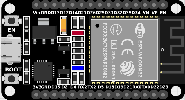
Pin Configuration and Descriptions

The ESP32 features multiple pins, including a dedicated power pin. Below is a table describing the key pins:

Power and Ground Pins

Pin Name Description
VIN Input voltage pin (3.3V - 5V)
3V3 Regulated 3.3V output
GND Ground

GPIO Pins

Pin Name Description
GPIO0 General-purpose I/O, boot mode pin
GPIO2 General-purpose I/O
GPIO4 General-purpose I/O
GPIO5 General-purpose I/O
GPIO12 General-purpose I/O
GPIO13 General-purpose I/O
GPIO14 General-purpose I/O
GPIO15 General-purpose I/O

Note: The ESP32 has additional GPIO pins and specialized pins for ADC, DAC, PWM, and I2C. Refer to the full datasheet for a complete pinout.

Usage Instructions

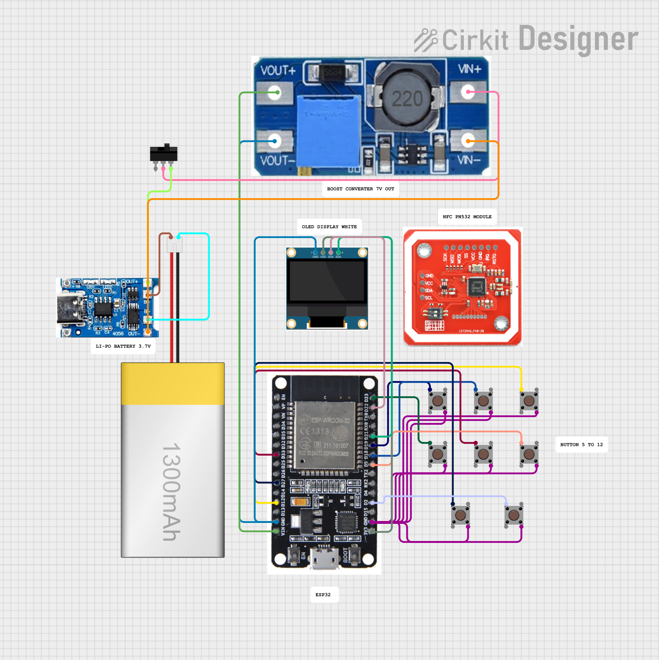
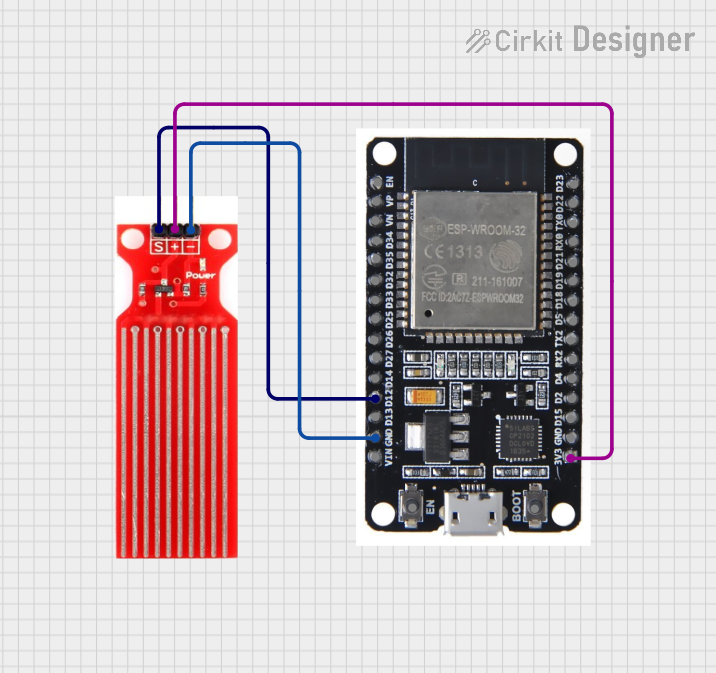
How to Use the ESP32 in a Circuit

  1. Powering the ESP32:

    • Connect the VIN pin to a 5V power source or use the 3V3 pin for a regulated 3.3V input.
    • Ensure the GND pin is connected to the ground of the power source.
  2. Programming the ESP32:

    • Use a USB-to-serial adapter or a development board with a built-in USB interface.
    • Install the ESP32 board package in the Arduino IDE or use the ESP-IDF framework for advanced development.
  3. Connecting Peripherals:

    • Use the GPIO pins to connect sensors, actuators, or other peripherals.
    • Ensure proper voltage levels and use level shifters if necessary.

Important Considerations and Best Practices

  • Power Supply: Use a stable power source to avoid voltage fluctuations that may cause the ESP32 to reset.
  • Boot Mode: Ensure GPIO0 is pulled low during boot to enter programming mode.
  • Heat Management: The ESP32 may generate heat during operation. Ensure proper ventilation or use a heatsink if necessary.
  • Wi-Fi Interference: Avoid placing the ESP32 near metal objects or other devices that may interfere with the Wi-Fi signal.

Example Code for Arduino UNO

Below is an example of how to use the ESP32 with an Arduino UNO to read data from a sensor and send it over Wi-Fi:

#include <WiFi.h> // Include the Wi-Fi library for ESP32

// Replace with your network credentials
const char* ssid = "Your_SSID";
const char* password = "Your_PASSWORD";

void setup() {
  Serial.begin(115200); // Initialize serial communication
  delay(1000);

  // Connect to Wi-Fi
  Serial.print("Connecting to Wi-Fi");
  WiFi.begin(ssid, password);
  while (WiFi.status() != WL_CONNECTED) {
    delay(500);
    Serial.print(".");
  }
  Serial.println("\nConnected to Wi-Fi");
}

void loop() {
  // Example: Print the ESP32's IP address
  Serial.print("ESP32 IP Address: ");
  Serial.println(WiFi.localIP());
  delay(5000); // Wait for 5 seconds before repeating
}

Note: Replace Your_SSID and Your_PASSWORD with your Wi-Fi network credentials.

Troubleshooting and FAQs

Common Issues and Solutions

  1. ESP32 Not Powering On:

    • Ensure the power source provides sufficient current (at least 500mA).
    • Check the connections to the VIN or 3V3 pin and GND.
  2. Wi-Fi Connection Fails:

    • Verify the SSID and password are correct.
    • Ensure the Wi-Fi network is within range and not overloaded.
  3. ESP32 Keeps Resetting:

    • Check for voltage drops or unstable power supply.
    • Add a capacitor (e.g., 10µF) across the power pins to stabilize the voltage.
  4. GPIO Pins Not Responding:

    • Ensure the pins are not being used for other functions (e.g., boot mode).
    • Check for proper pull-up or pull-down resistors if required.

FAQs

Q: Can the ESP32 operate on 5V directly?
A: No, the ESP32 operates at 3.3V. However, the VIN pin can accept 5V, which is regulated down to 3.3V internally.

Q: How do I reset the ESP32?
A: Press the reset button on the development board or momentarily connect the EN pin to GND.

Q: Can I use the ESP32 with a battery?
A: Yes, you can use a LiPo battery with a voltage regulator to provide 3.3V or connect it to the VIN pin if the battery provides 5V.

Q: Is the ESP32 compatible with Arduino libraries?
A: Yes, the ESP32 is compatible with many Arduino libraries, but some may require modifications.