Cirkit Designer Logo
Cirkit Designer
Your all-in-one circuit design IDE
Home / 
Component Documentation

How to Use Adafruit FONA 3G Breakout: Examples, Pinouts, and Specs

Image of Adafruit FONA 3G Breakout
Cirkit Designer LogoDesign with Adafruit FONA 3G Breakout in Cirkit Designer

Introduction

The Adafruit FONA 3G Breakout is a compact and reliable cellular module that enables microcontroller projects to access 3G data networks. It's perfect for IoT devices, remote monitoring, and mobile applications where communication over a cellular network is required. The breakout board is designed to work with a standard-sized SIM card and includes an SMA connector for an external antenna to ensure optimal signal reception.

Explore Projects Built with Adafruit FONA 3G Breakout

Use Cirkit Designer to design, explore, and prototype these projects online. Some projects support real-time simulation. Click "Open Project" to start designing instantly!
Raspberry Pi 4B-Based GPS and GSM Tracking System with Audio Feedback
Image of unlimited range: A project utilizing Adafruit FONA 3G Breakout in a practical application
This circuit features a Raspberry Pi 4B as the central processing unit, interfaced with a GPS NEO-6M V2 module for location tracking and an Adafruit FONA 808 Shield for cellular communication. It includes a PAM8406 5V Digital Audio Amplifier connected to an Adafruit STEMMA Speaker for audio output, and a Condenser Microphone connected to the FONA 808 for audio input. Power management is handled by a 12V battery connected to a voltage regulator that steps down the voltage to 5V and 3V required by the various components.
Cirkit Designer LogoOpen Project in Cirkit Designer
Arduino Mega 2560 Based Security System with Fingerprint Authentication and SMS Alerts
Image of Door security system: A project utilizing Adafruit FONA 3G Breakout in a practical application
This circuit features an Arduino Mega 2560 microcontroller interfaced with a SIM800L GSM module, two fingerprint scanners, an I2C LCD display, an IR sensor, and a piezo buzzer. Power management is handled by a PowerBoost 1000 Basic Pad USB, a TP4056 charging module, and a Li-ion 18650 battery, with an option to use a Mini AC-DC 110V-230V to 5V 700mA module for direct power supply. The primary functionality appears to be a security system with GSM communication capabilities, biometric access control, and visual/audible feedback.
Cirkit Designer LogoOpen Project in Cirkit Designer
Arduino UNO with A9G GSM/GPRS and Dual VL53L1X Distance Sensors
Image of TED CIRCUIT : A project utilizing Adafruit FONA 3G Breakout in a practical application
This circuit features an Arduino UNO microcontroller interfaced with an A9G GSM/GPRS+GPS/BDS module and two VL53L1X time-of-flight distance sensors. The A9G module is connected to the Arduino via serial communication for GPS and GSM functionalities, while both VL53L1X sensors are connected through I2C with shared SDA and SCL lines and individual SHUT pins for selective sensor activation. The Arduino is programmed to control these peripherals, although the specific functionality is not detailed in the provided code.
Cirkit Designer LogoOpen Project in Cirkit Designer
Arduino UNO and SIM900A GSM Module Interface
Image of sim900a : A project utilizing Adafruit FONA 3G Breakout in a practical application
This circuit connects an Arduino UNO microcontroller with a SIM900A GSM/GPRS module, enabling cellular communication capabilities. The Arduino's digital pins D7 and D8 are connected to the SIM900A's 5VT and 5VR pins, likely for serial communication. A separate 5V connector provides power to the SIM900A, with common ground connections established between all components.
Cirkit Designer LogoOpen Project in Cirkit Designer

Explore Projects Built with Adafruit FONA 3G Breakout

Use Cirkit Designer to design, explore, and prototype these projects online. Some projects support real-time simulation. Click "Open Project" to start designing instantly!
Image of unlimited range: A project utilizing Adafruit FONA 3G Breakout in a practical application
Raspberry Pi 4B-Based GPS and GSM Tracking System with Audio Feedback
This circuit features a Raspberry Pi 4B as the central processing unit, interfaced with a GPS NEO-6M V2 module for location tracking and an Adafruit FONA 808 Shield for cellular communication. It includes a PAM8406 5V Digital Audio Amplifier connected to an Adafruit STEMMA Speaker for audio output, and a Condenser Microphone connected to the FONA 808 for audio input. Power management is handled by a 12V battery connected to a voltage regulator that steps down the voltage to 5V and 3V required by the various components.
Cirkit Designer LogoOpen Project in Cirkit Designer
Image of Door security system: A project utilizing Adafruit FONA 3G Breakout in a practical application
Arduino Mega 2560 Based Security System with Fingerprint Authentication and SMS Alerts
This circuit features an Arduino Mega 2560 microcontroller interfaced with a SIM800L GSM module, two fingerprint scanners, an I2C LCD display, an IR sensor, and a piezo buzzer. Power management is handled by a PowerBoost 1000 Basic Pad USB, a TP4056 charging module, and a Li-ion 18650 battery, with an option to use a Mini AC-DC 110V-230V to 5V 700mA module for direct power supply. The primary functionality appears to be a security system with GSM communication capabilities, biometric access control, and visual/audible feedback.
Cirkit Designer LogoOpen Project in Cirkit Designer
Image of TED CIRCUIT : A project utilizing Adafruit FONA 3G Breakout in a practical application
Arduino UNO with A9G GSM/GPRS and Dual VL53L1X Distance Sensors
This circuit features an Arduino UNO microcontroller interfaced with an A9G GSM/GPRS+GPS/BDS module and two VL53L1X time-of-flight distance sensors. The A9G module is connected to the Arduino via serial communication for GPS and GSM functionalities, while both VL53L1X sensors are connected through I2C with shared SDA and SCL lines and individual SHUT pins for selective sensor activation. The Arduino is programmed to control these peripherals, although the specific functionality is not detailed in the provided code.
Cirkit Designer LogoOpen Project in Cirkit Designer
Image of sim900a : A project utilizing Adafruit FONA 3G Breakout in a practical application
Arduino UNO and SIM900A GSM Module Interface
This circuit connects an Arduino UNO microcontroller with a SIM900A GSM/GPRS module, enabling cellular communication capabilities. The Arduino's digital pins D7 and D8 are connected to the SIM900A's 5VT and 5VR pins, likely for serial communication. A separate 5V connector provides power to the SIM900A, with common ground connections established between all components.
Cirkit Designer LogoOpen Project in Cirkit Designer

Common Applications and Use Cases

  • Remote data logging and telemetry
  • SMS-based remote control
  • Location tracking with GPS functionality
  • Voice calls from microcontroller projects
  • Internet connectivity for IoT devices

Technical Specifications

Key Technical Details

  • Networks: UMTS/HSDPA (3G) and GSM/GPRS/EDGE (2G)
  • Frequency Bands: 850/900/1800/1900 MHz (2G) and 850/1900/2100 MHz (3G)
  • Data Rates: 384 Kbps (3G), Class 12 (GPRS)
  • Supply Voltage: 3.4-4.2V
  • Operating Temperature: -40°C to +85°C

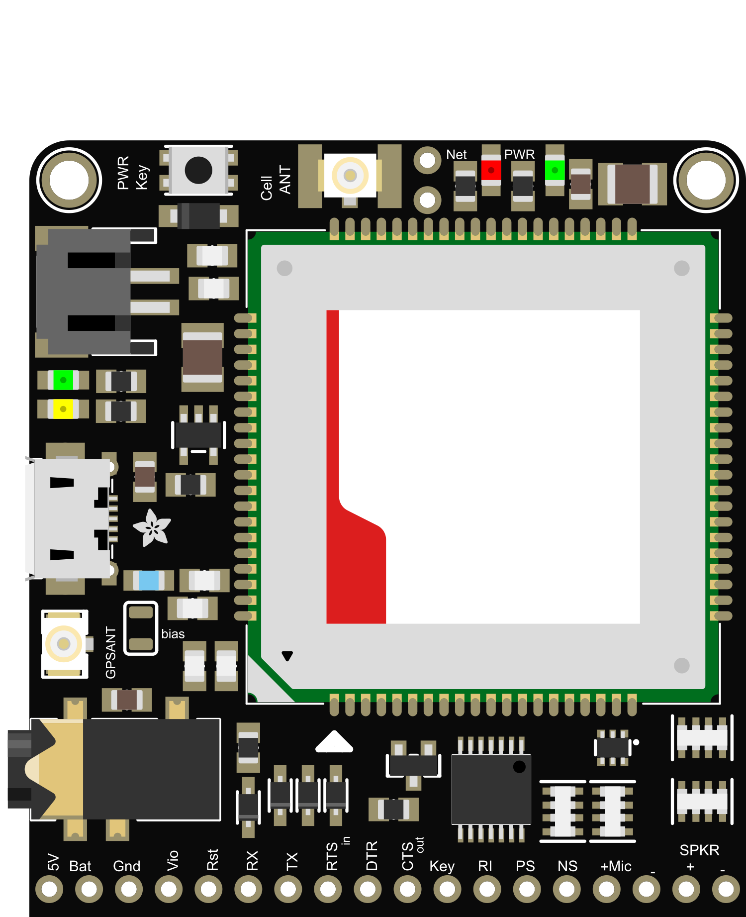
Pin Configuration and Descriptions

Pin Number Name Description
1 Vio Digital supply voltage (3.3V-5V)
2 GND Ground connection
3 Key Active low to turn on the module
4 RX UART receive pin
5 TX UART transmit pin
6 RST Active low reset pin
... ... ...

Usage Instructions

How to Use the Component in a Circuit

  1. Power Supply: Connect the Vio pin to a 3.3V-5V power source, and connect the GND pin to the ground.
  2. SIM Card: Insert a standard-sized SIM card with data capabilities into the SIM card slot.
  3. Antenna: Attach a compatible 3G antenna to the SMA connector.
  4. UART Communication: Connect the RX and TX pins to the corresponding TX and RX pins of your microcontroller.
  5. Module Activation: Pull the Key pin low to turn on the module.

Important Considerations and Best Practices

  • Ensure that the power supply can provide sufficient current for the module during peak operations.
  • Use a level shifter if your microcontroller operates at a different logic level than the FONA 3G's 3.3V-5V range.
  • Always power down the module before inserting or removing the SIM card to prevent damage.
  • For optimal network reception, place the antenna in a location with minimal obstructions.

Troubleshooting and FAQs

Common Issues

  • No Network Connection: Ensure the SIM card is activated and has a data plan. Check the antenna connections and placement.
  • Module Does Not Power On: Verify the power supply and Key pin connections. Ensure the power supply is within the specified voltage range.
  • Serial Communication Failure: Check the UART connections and ensure the baud rate matches the module's default setting.

Solutions and Tips for Troubleshooting

  • If the module is unresponsive, perform a hard reset by pulling the RST pin low for a few seconds.
  • Use the module's status LED indicators to diagnose power and network connectivity issues.
  • Consult the Adafruit FONA 3G Breakout forums and community for additional support and resources.

FAQs

Q: Can I make voice calls with the FONA 3G? A: Yes, the FONA 3G supports voice calls. You will need to connect a speaker and microphone to the appropriate pins.

Q: What is the default baud rate for UART communication? A: The default baud rate is 115200 bps, but it can be adjusted using AT commands.

Q: How do I update the firmware on the FONA 3G? A: Firmware updates can be performed using the USB interface and the provided software tools from Adafruit.

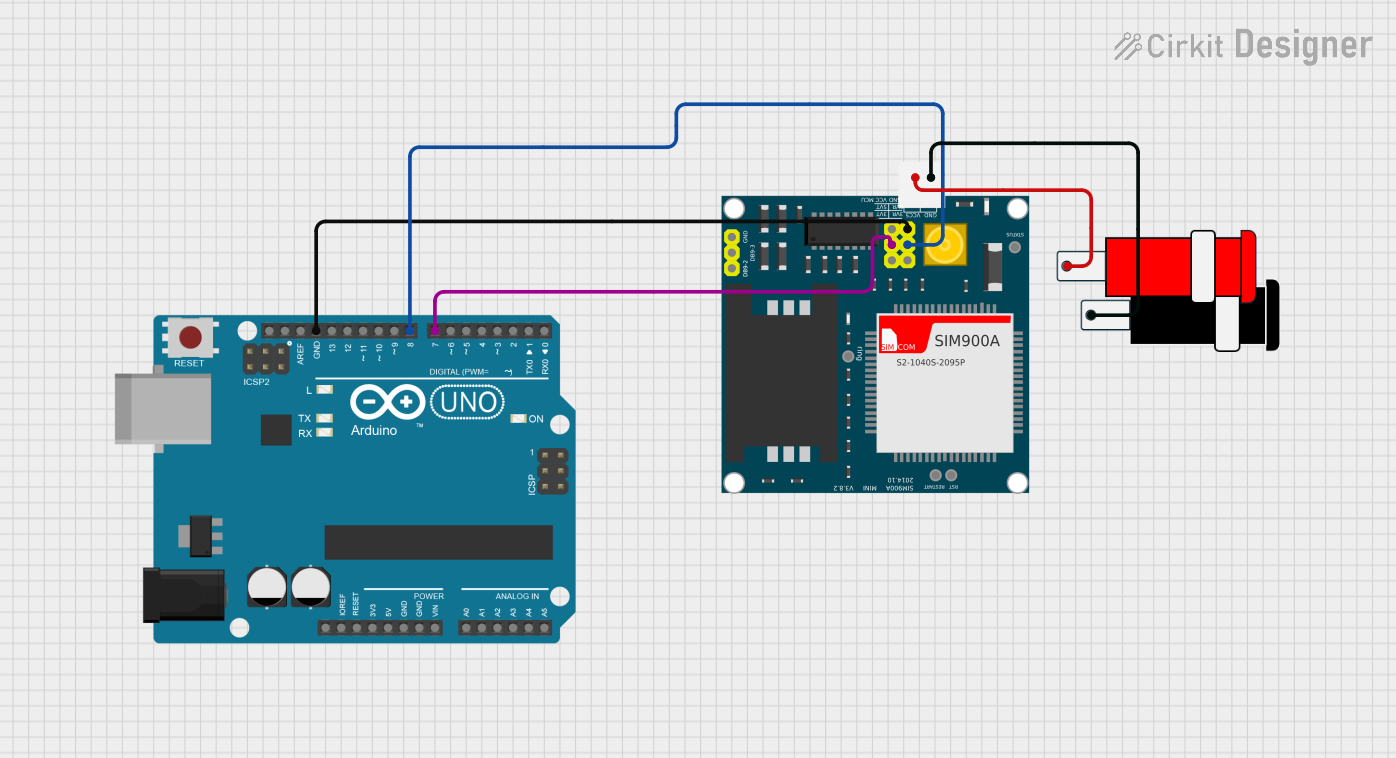
Example Code for Arduino UNO

#include <SoftwareSerial.h>

// Pin definitions
const int FONA_RX = 2; // FONA TX
const int FONA_TX = 3; // FONA RX
const int FONA_RST = 4; // FONA RST

// Create a software serial object
SoftwareSerial fonaSerial(FONA_RX, FONA_TX);

void setup() {
  pinMode(FONA_RST, OUTPUT);
  digitalWrite(FONA_RST, HIGH); // Deactivate reset
  fonaSerial.begin(115200); // Match the default baud rate of FONA 3G
  Serial.begin(115200); // Start serial communication with the computer
  Serial.println("FONA 3G test");
}

void loop() {
  // Code to interact with the FONA 3G module
  // For example, sending an SMS, making a call, or using data
}

Remember to keep the code comments concise and within the 80 character line length limit. This example demonstrates how to initialize the FONA 3G module with an Arduino UNO using a software serial connection. Additional functionality, such as sending SMS or making calls, can be implemented using the appropriate AT commands sent through the fonaSerial object.