Cirkit Designer
Your all-in-one circuit design IDE
Home /
Component Documentation
How to Use GPS: Examples, Pinouts, and Specs
Introduction
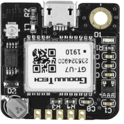
The NEO-6M GPS module, manufactured by Beffkkip, is a high-performance Global Positioning System (GPS) receiver. It provides accurate location and time information in all weather conditions, anywhere on or near the Earth. This module is widely used in various applications such as vehicle tracking, personal navigation devices, and geographic surveying.
Explore Projects Built with GPS
ESP32-Based GPS Tracker with OLED Display and Telegram Integration

This circuit is a GPS-based tracking system that uses an ESP32 microcontroller to receive GPS data from a NEO 6M module and display the coordinates on a 1.3" OLED screen. It also features WiFi connectivity to send location updates to a remote server, potentially for applications such as asset tracking or navigation assistance.
ESP32-Based GPS Tracker with OLED Display and Firebase Integration

This circuit is a GPS tracking system that uses an ESP32 microcontroller to read location data from a NEO-6M GPS module and display information on a 0.96" OLED screen. The system is powered by a 2000mAh battery with a lithium-ion charger, and it uploads the GPS data to Firebase via WiFi. Additional components include an MPU6050 accelerometer/gyroscope for motion sensing and a buzzer for alerts.
Arduino Nano GPS Tracker with GSM and OLED Display

This circuit is a GPS tracking system that uses an Arduino Nano to interface with a SIM800L GSM module, a GPS NEO 6M module, and a 1.3-inch OLED display. The Arduino collects GPS data, displays it on the OLED screen, and sends the coordinates via SMS using the GSM module.
Arduino UNO-Based GPS and GSM-Enabled Vibration Sensor System with Motor Control
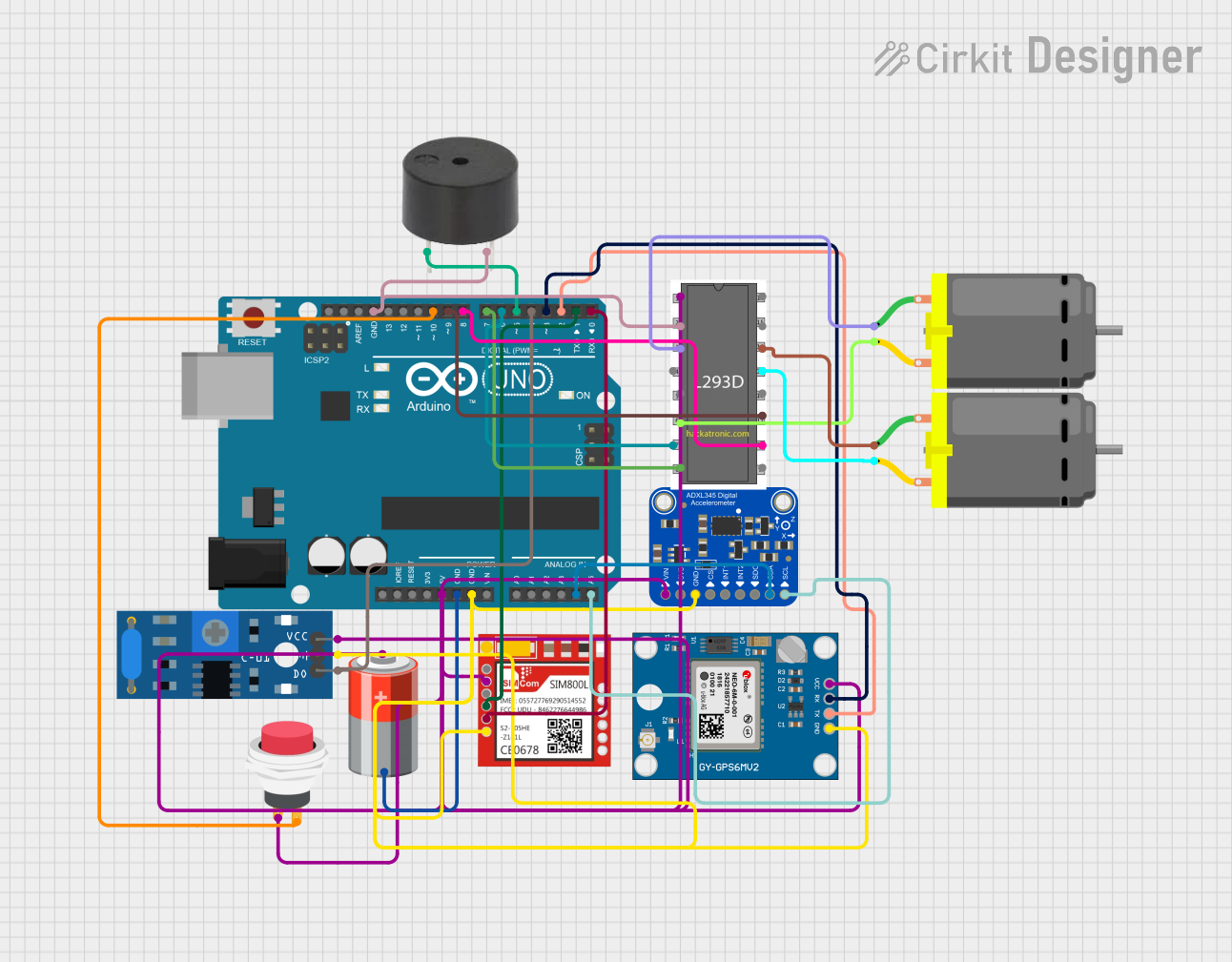
This circuit is a GPS-based tracking system with vibration detection and motor control capabilities. It uses an Arduino UNO to interface with a Neo 6M GPS module for location data, a Sim800l module for GSM communication, an ADXL345 accelerometer for motion sensing, and an SW-420 vibration sensor to detect vibrations. The system also includes a motor driver to control two DC motors and a buzzer for alerts, all powered by a 5V battery.
Explore Projects Built with GPS
ESP32-Based GPS Tracker with OLED Display and Telegram Integration
This circuit is a GPS-based tracking system that uses an ESP32 microcontroller to receive GPS data from a NEO 6M module and display the coordinates on a 1.3" OLED screen. It also features WiFi connectivity to send location updates to a remote server, potentially for applications such as asset tracking or navigation assistance.
ESP32-Based GPS Tracker with OLED Display and Firebase Integration
This circuit is a GPS tracking system that uses an ESP32 microcontroller to read location data from a NEO-6M GPS module and display information on a 0.96" OLED screen. The system is powered by a 2000mAh battery with a lithium-ion charger, and it uploads the GPS data to Firebase via WiFi. Additional components include an MPU6050 accelerometer/gyroscope for motion sensing and a buzzer for alerts.
Arduino Nano GPS Tracker with GSM and OLED Display
This circuit is a GPS tracking system that uses an Arduino Nano to interface with a SIM800L GSM module, a GPS NEO 6M module, and a 1.3-inch OLED display. The Arduino collects GPS data, displays it on the OLED screen, and sends the coordinates via SMS using the GSM module.
Arduino UNO-Based GPS and GSM-Enabled Vibration Sensor System with Motor Control
This circuit is a GPS-based tracking system with vibration detection and motor control capabilities. It uses an Arduino UNO to interface with a Neo 6M GPS module for location data, a Sim800l module for GSM communication, an ADXL345 accelerometer for motion sensing, and an SW-420 vibration sensor to detect vibrations. The system also includes a motor driver to control two DC motors and a buzzer for alerts, all powered by a 5V battery.
Technical Specifications
Key Technical Details
| Parameter | Value |
|---|---|
| Manufacturer | Beffkkip |
| Part ID | NEO-6M |
| Operating Voltage | 2.7V - 3.6V |
| Power Consumption | 45mA @ 3.0V |
| Position Accuracy | 2.5m CEP |
| Velocity Accuracy | 0.1 m/s |
| Time Accuracy | 30 ns |
| Cold Start Time | 27 s |
| Warm Start Time | 27 s |
| Hot Start Time | 1 s |
| Max Update Rate | 5 Hz |
| Communication | UART, TTL |
| Antenna | External Active Antenna |
Pin Configuration and Descriptions
| Pin Number | Pin Name | Description |
|---|---|---|
| 1 | GND | Ground |
| 2 | VCC | Power Supply (3.3V) |
| 3 | TX | Transmit Data (UART) |
| 4 | RX | Receive Data (UART) |
| 5 | PPS | Pulse Per Second (Time Synchronization) |
Usage Instructions
How to Use the NEO-6M GPS Module in a Circuit
- Power Supply: Connect the VCC pin to a 3.3V power supply and the GND pin to the ground.
- UART Communication: Connect the TX pin of the GPS module to the RX pin of the microcontroller (e.g., Arduino UNO) and the RX pin of the GPS module to the TX pin of the microcontroller.
- Antenna: Attach the external active antenna to the GPS module for better signal reception.
Important Considerations and Best Practices
- Power Supply: Ensure a stable 3.3V power supply to avoid damage to the module.
- Antenna Placement: Place the antenna in an open area with a clear view of the sky for optimal signal reception.
- UART Configuration: Set the UART baud rate to 9600 bps for communication with the GPS module.
- Data Parsing: Use libraries or write custom code to parse the NMEA sentences received from the GPS module.
Example Code for Arduino UNO
#include <SoftwareSerial.h>
#include <TinyGPS++.h>

// Create a SoftwareSerial object for GPS communication
SoftwareSerial gpsSerial(4, 3); // RX, TX

// Create a TinyGPS++ object
TinyGPSPlus gps;

void setup() {
  Serial.begin(9600); // Initialize serial communication with the PC
  gpsSerial.begin(9600); // Initialize serial communication with the GPS module
  Serial.println("NEO-6M GPS Module Test");
}

void loop() {
  while (gpsSerial.available() > 0) {
    gps.encode(gpsSerial.read()); // Decode the data from the GPS module

    if (gps.location.isUpdated()) {
      // Print the latitude and longitude
      Serial.print("Latitude: ");
      Serial.println(gps.location.lat(), 6);
      Serial.print("Longitude: ");
      Serial.println(gps.location.lng(), 6);
    }
  }
}
Troubleshooting and FAQs
Common Issues and Solutions
No GPS Fix:
- Solution: Ensure the antenna has a clear view of the sky. It may take a few minutes to get the first fix.
No Data Received:
- Solution: Check the connections between the GPS module and the microcontroller. Ensure the baud rate is set correctly.
Inaccurate Location Data:
- Solution: Verify the antenna placement and ensure there are no obstructions. Check for any sources of interference.
FAQs
Q1: Can I use a 5V power supply for the NEO-6M GPS module?
- A1: No, the NEO-6M GPS module operates at 3.3V. Using a 5V power supply may damage the module.
Q2: How long does it take to get a GPS fix?
- A2: The cold start time is approximately 27 seconds, while the hot start time is around 1 second.
Q3: Can I use the NEO-6M GPS module indoors?
- A3: GPS modules generally require a clear view of the sky for accurate positioning. Indoor use may result in poor signal reception and inaccurate data.
Q4: What is the purpose of the PPS pin?
- A4: The PPS (Pulse Per Second) pin provides a precise timing signal that can be used for time synchronization in various applications.
By following this documentation, users can effectively integrate the NEO-6M GPS module into their projects and troubleshoot common issues.