Cirkit Designer Logo
Cirkit Designer
Your all-in-one circuit design IDE
Home / 
Component Documentation

How to Use MAX30102: Examples, Pinouts, and Specs

Image of MAX30102
Cirkit Designer LogoDesign with MAX30102 in Cirkit Designer

Introduction

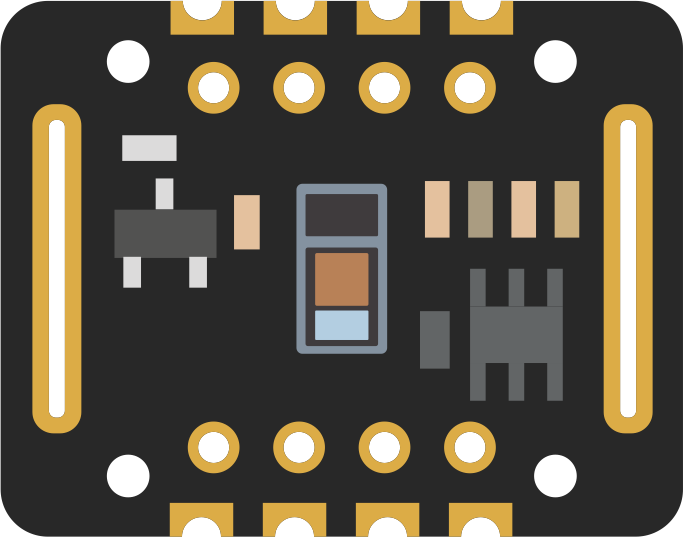
The MAX30102 is an integrated pulse oximetry and heart-rate monitor bio-sensor module. It is designed for the wearable health market and features internal LEDs, photodetectors, optical elements, and low-noise electronics with ambient light rejection. The device is commonly used in fitness trackers, smartwatches, and medical monitoring devices to measure blood oxygen saturation (SpO2) levels and heart rate through the skin.

Explore Projects Built with MAX30102

Use Cirkit Designer to design, explore, and prototype these projects online. Some projects support real-time simulation. Click "Open Project" to start designing instantly!
Battery-Powered Health Monitoring System with Nucleo WB55RG and OLED Display
Image of Pulsefex: A project utilizing MAX30102 in a practical application
This circuit is a multi-sensor data acquisition system that uses a Nucleo WB55RG microcontroller to interface with a digital temperature sensor (TMP102), a pulse oximeter and heart-rate sensor (MAX30102), and a 0.96" OLED display via I2C. Additionally, it includes a Sim800l module for GSM communication, powered by a 3.7V LiPo battery.
Cirkit Designer LogoOpen Project in Cirkit Designer
ESP32-Based Multi-Sensor Health Monitoring System with Bluetooth Connectivity
Image of circuit diagram: A project utilizing MAX30102 in a practical application
This circuit features an ESP32-WROOM-32UE microcontroller as the central processing unit, interfacing with a variety of sensors and modules. It includes a MAX30100 pulse oximeter and heart-rate sensor, an MLX90614 infrared thermometer, an HC-05 Bluetooth module for wireless communication, and a Neo 6M GPS module for location tracking. All components are powered by a common voltage supply and are connected to specific GPIO pins on the ESP32 for data exchange, with the sensors using I2C communication and the modules using UART.
Cirkit Designer LogoOpen Project in Cirkit Designer
ESP32 and MAX30100 Pulse Oximeter
Image of t: A project utilizing MAX30102 in a practical application
This circuit features an ESP32 microcontroller connected to a MAX30100 sensor, which is likely used for measuring pulse oximetry. The ESP32 is interfaced with the MAX30100 via I2C communication, as indicated by the SDA and SCL connections. Power is supplied to both the ESP32 and the MAX30100 by a 5V battery, with common ground established across the components.
Cirkit Designer LogoOpen Project in Cirkit Designer
ESP32-Based Health Monitoring System with Bluetooth and GPS
Image of circuit diagram: A project utilizing MAX30102 in a practical application
This circuit integrates an ESP32 microcontroller with various sensors and modules, including a MAX30100 pulse oximeter, an MLX90614 infrared thermometer, a Neo 6M GPS module, and an HC-05 Bluetooth module. The ESP32 collects data from these sensors and modules via I2C and UART interfaces, enabling wireless communication and GPS tracking capabilities.
Cirkit Designer LogoOpen Project in Cirkit Designer

Explore Projects Built with MAX30102

Use Cirkit Designer to design, explore, and prototype these projects online. Some projects support real-time simulation. Click "Open Project" to start designing instantly!
Image of Pulsefex: A project utilizing MAX30102 in a practical application
Battery-Powered Health Monitoring System with Nucleo WB55RG and OLED Display
This circuit is a multi-sensor data acquisition system that uses a Nucleo WB55RG microcontroller to interface with a digital temperature sensor (TMP102), a pulse oximeter and heart-rate sensor (MAX30102), and a 0.96" OLED display via I2C. Additionally, it includes a Sim800l module for GSM communication, powered by a 3.7V LiPo battery.
Cirkit Designer LogoOpen Project in Cirkit Designer
Image of circuit diagram: A project utilizing MAX30102 in a practical application
ESP32-Based Multi-Sensor Health Monitoring System with Bluetooth Connectivity
This circuit features an ESP32-WROOM-32UE microcontroller as the central processing unit, interfacing with a variety of sensors and modules. It includes a MAX30100 pulse oximeter and heart-rate sensor, an MLX90614 infrared thermometer, an HC-05 Bluetooth module for wireless communication, and a Neo 6M GPS module for location tracking. All components are powered by a common voltage supply and are connected to specific GPIO pins on the ESP32 for data exchange, with the sensors using I2C communication and the modules using UART.
Cirkit Designer LogoOpen Project in Cirkit Designer
Image of t: A project utilizing MAX30102 in a practical application
ESP32 and MAX30100 Pulse Oximeter
This circuit features an ESP32 microcontroller connected to a MAX30100 sensor, which is likely used for measuring pulse oximetry. The ESP32 is interfaced with the MAX30100 via I2C communication, as indicated by the SDA and SCL connections. Power is supplied to both the ESP32 and the MAX30100 by a 5V battery, with common ground established across the components.
Cirkit Designer LogoOpen Project in Cirkit Designer
Image of circuit diagram: A project utilizing MAX30102 in a practical application
ESP32-Based Health Monitoring System with Bluetooth and GPS
This circuit integrates an ESP32 microcontroller with various sensors and modules, including a MAX30100 pulse oximeter, an MLX90614 infrared thermometer, a Neo 6M GPS module, and an HC-05 Bluetooth module. The ESP32 collects data from these sensors and modules via I2C and UART interfaces, enabling wireless communication and GPS tracking capabilities.
Cirkit Designer LogoOpen Project in Cirkit Designer

Technical Specifications

Key Technical Details

  • Power Supply Voltage (VCC): 1.8V to 3.3V
  • Operating Current (Typical): 600µA (LEDs on), 7µA (Standby)
  • Peak LED Output Current: 50mA
  • LED Wavelengths: 660nm (Red), 880/905nm (IR)
  • Communication Interface: I2C (up to 400kHz)
  • FIFO Memory: 32-bit word x 32 data words
  • Resolution: 16-bit ADC
  • Operating Temperature Range: -40°C to +85°C

Pin Configuration and Descriptions

Pin Number Name Description
1 SDA I2C Serial Data
2 SCL I2C Serial Clock
3 INT Interrupt Output
4 IRD IR LED Driver
5 RD Red LED Driver
6 GND Ground Connection
7 VCC Power Supply Input

Usage Instructions

Integration into a Circuit

To use the MAX30102 in a circuit:

  1. Connect VCC to a 1.8V to 3.3V power source.
  2. Connect GND to the system ground.
  3. Interface the SDA and SCL pins with the I2C bus of a microcontroller, such as an Arduino UNO.
  4. The INT pin can be connected to an interrupt-capable GPIO pin on the microcontroller to handle interrupt-driven data acquisition.

Best Practices

  • Ensure that the power supply is clean and within the specified voltage range.
  • Use pull-up resistors on the SDA and SCL lines, typically 4.7kΩ to 10kΩ.
  • Keep the I2C bus lines as short as possible to reduce noise and interference.
  • Avoid placing the sensor under direct sunlight or strong artificial light sources to prevent inaccurate readings.

Example Code for Arduino UNO

#include <Wire.h>

// MAX30102 I2C address (usually 0x57)
#define MAX30102_ADDRESS 0x57

void setup() {
  Serial.begin(9600);
  Wire.begin();

  // Initialize MAX30102 with default settings
  max30102_init();
}

void loop() {
  // Read data from MAX30102
  int heartRate = readHeartRate();
  int spO2 = readSpO2();

  // Output the heart rate and SpO2 values
  Serial.print("Heart Rate: ");
  Serial.print(heartRate);
  Serial.print(" bpm, SpO2: ");
  Serial.print(spO2);
  Serial.println(" %");

  // Small delay between readings
  delay(1000);
}

void max30102_init() {
  // Add initialization code specific to MAX30102
}

int readHeartRate() {
  // Add code to read heart rate from MAX30102
  return 0; // Placeholder return value
}

int readSpO2() {
  // Add code to read SpO2 from MAX30102
  return 0; // Placeholder return value
}

Note: The above code is a template and does not contain the actual implementation for initializing the MAX30102 or reading data from it. You will need to use a library or write additional functions to communicate with the device and process the sensor data.

Troubleshooting and FAQs

Common Issues

  • No Data Output: Ensure that the I2C connections are correct and that the device is properly powered.
  • Inaccurate Readings: Check for proper skin contact and avoid direct exposure to external light sources.
  • I2C Communication Errors: Verify pull-up resistors are installed and check for noise on the I2C lines.

Solutions and Tips

  • If you encounter no data output, double-check the I2C address and wiring connections.
  • For inaccurate readings, make sure the sensor is placed firmly against the skin without any obstructions.
  • Use an oscilloscope to check the integrity of the I2C signals if communication errors persist.

FAQs

Q: Can the MAX30102 be used without an Arduino? A: Yes, the MAX30102 can be interfaced with any microcontroller that supports I2C communication.

Q: How can I improve the accuracy of the sensor? A: Ensure stable contact with the skin, avoid motion artifacts, and shield the sensor from external light.

Q: Is the MAX30102 suitable for medical applications? A: While the MAX30102 can provide useful data for health monitoring, it is not a substitute for a medical-grade device. Always consult with a healthcare professional for medical use.

Q: What libraries can be used with the MAX30102 for Arduino? A: There are several libraries available for interfacing with the MAX30102, such as the "MAX30105" library by SparkFun, which is also compatible with the MAX30102.