How to Use optocoupler pc817 4 channel: Examples, Pinouts, and Specs
Introduction
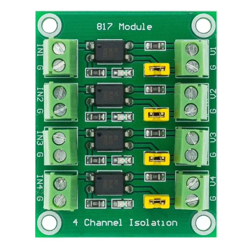
The PC817 is a 4-channel optocoupler designed to provide electrical isolation between its input and output. Each channel consists of an infrared LED and a phototransistor, enabling signal transmission without direct electrical connection. This isolation is crucial for protecting sensitive low-voltage circuits, such as microcontrollers, from high-voltage or noisy environments.
Common applications of the PC817 4-channel optocoupler include:
- Interfacing microcontrollers with high-voltage circuits
- Signal isolation in industrial control systems
- Noise suppression in communication lines
- Switching and control in power electronics
Explore Projects Built with optocoupler pc817 4 channel


Explore Projects Built with optocoupler pc817 4 channel
Technical Specifications
The PC817 4-channel optocoupler has the following key technical specifications:
| Parameter | Value |
|---|---|
| Channels | 4 |
| Input Type | Infrared LED |
| Output Type | Phototransistor |
| Isolation Voltage | 5000 Vrms (minimum) |
| Forward Voltage (LED) | 1.2V (typical), 1.4V (maximum) |
| Forward Current (LED) | 20mA (typical), 50mA (maximum) |
| Collector-Emitter Voltage | 35V (maximum) |
| Current Transfer Ratio (CTR) | 50% to 600% (depending on model) |
| Operating Temperature Range | -30°C to +100°C |
| Package Type | DIP-16 |
Pin Configuration and Descriptions
The PC817 4-channel optocoupler is housed in a 16-pin DIP package. The pin configuration is as follows:
| Pin Number | Name | Description |
|---|---|---|
| 1, 3, 5, 7 | Anode (Input) | Positive terminal of the LED for each channel. |
| 2, 4, 6, 8 | Cathode (Input) | Negative terminal of the LED for each channel. |
| 9, 11, 13, 15 | Emitter (Output) | Emitter terminal of the phototransistor. |
| 10, 12, 14, 16 | Collector (Output) | Collector terminal of the phototransistor. |
Usage Instructions
How to Use the PC817 in a Circuit
Connect the Input Side (LED):
- Connect the anode (positive terminal) of the LED to the signal source.
- Use a current-limiting resistor in series with the LED to prevent overcurrent. The resistor value can be calculated using Ohm's Law:
[ R = \frac{V_{source} - V_{forward}}{I_{forward}} ] where ( V_{source} ) is the input voltage, ( V_{forward} ) is the forward voltage of the LED (1.2V typical), and ( I_{forward} ) is the desired forward current (e.g., 10mA).
Connect the Output Side (Phototransistor):
- Connect the collector terminal to the positive supply voltage through a pull-up resistor.
- The emitter terminal is connected to ground.
- The output signal can be read at the collector terminal. When the LED is on, the phototransistor conducts, pulling the output low.
Power Supply:
- Ensure the input and output circuits are powered separately to maintain isolation.
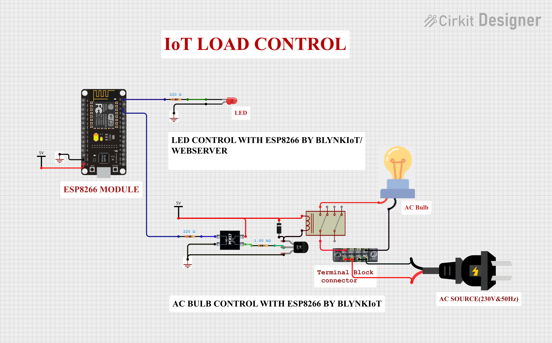
Example Circuit with Arduino UNO
Below is an example of how to connect one channel of the PC817 to an Arduino UNO to read a digital signal:
// Example code to read a signal from the PC817 optocoupler with Arduino UNO

const int optoInputPin = 2;  // Pin connected to the optocoupler output
const int ledPin = 13;       // Built-in LED for output indication

void setup() {
  pinMode(optoInputPin, INPUT);  // Set optocoupler output pin as input
  pinMode(ledPin, OUTPUT);       // Set LED pin as output
  Serial.begin(9600);            // Initialize serial communication
}

void loop() {
  int optoState = digitalRead(optoInputPin);  // Read the optocoupler output

  if (optoState == LOW) {
    // If optocoupler output is LOW, turn on the LED
    digitalWrite(ledPin, HIGH);
    Serial.println("Signal detected!");
  } else {
    // If optocoupler output is HIGH, turn off the LED
    digitalWrite(ledPin, LOW);
    Serial.println("No signal.");
  }

  delay(500);  // Wait for 500ms before reading again
}
Important Considerations and Best Practices
- Current Limiting Resistor: Always use a resistor in series with the LED to prevent damage due to excessive current.
- Pull-Up Resistor: Use an appropriate pull-up resistor on the phototransistor's collector to ensure proper signal levels.
- Isolation: Ensure that the input and output circuits are electrically isolated to prevent ground loops or accidental short circuits.
- Temperature Range: Operate the PC817 within its specified temperature range to avoid performance degradation.
Troubleshooting and FAQs
Common Issues and Solutions
No Output Signal:
- Cause: The LED may not be receiving sufficient current.
- Solution: Check the current-limiting resistor value and ensure the input voltage is sufficient to drive the LED.
Output Signal Always High:
- Cause: The phototransistor may not be conducting.
- Solution: Verify the LED is functioning and emitting light. Check the pull-up resistor value on the output side.
Output Signal Always Low:
- Cause: The phototransistor may be damaged or the pull-up resistor is too small.
- Solution: Replace the optocoupler if necessary and ensure the pull-up resistor value is appropriate.
Signal Distortion or Noise:
- Cause: High-frequency noise or improper grounding.
- Solution: Use decoupling capacitors and ensure proper grounding practices.
FAQs
Q: Can the PC817 be used for analog signal transmission?
A: The PC817 is primarily designed for digital signal isolation. While it can transmit analog signals, the response may be non-linear and limited by the phototransistor's characteristics.
Q: What is the maximum switching speed of the PC817?
A: The PC817 has a typical switching speed of 2-4 µs, making it suitable for low- to medium-speed applications.
Q: Can I use the PC817 with a 3.3V microcontroller?
A: Yes, but ensure the forward current of the LED is sufficient by selecting an appropriate current-limiting resistor.
Q: How do I calculate the pull-up resistor value?
A: The pull-up resistor value depends on the supply voltage and desired current. A typical value is 10kΩ for most applications.
By following this documentation, you can effectively use the PC817 4-channel optocoupler in your projects for reliable signal isolation and protection.