How to Use Led Module Yellow: Examples, Pinouts, and Specs
Introduction
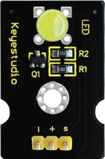
The Keyestudio LED Module Yellow (Part ID: KS0232) is a compact and versatile electronic component designed to emit yellow light when powered. It is widely used in various applications such as status indicators, visual displays, and decorative lighting. The module is easy to integrate into circuits and is compatible with microcontrollers like Arduino, making it an excellent choice for both beginners and experienced hobbyists.
Explore Projects Built with Led Module Yellow
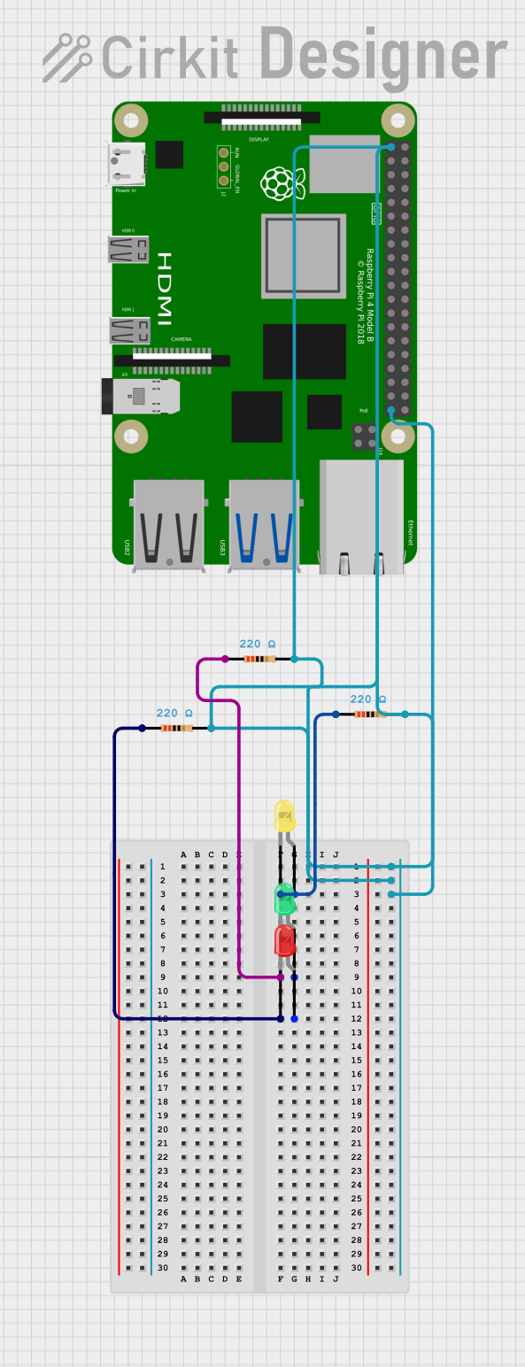
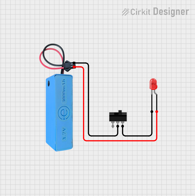
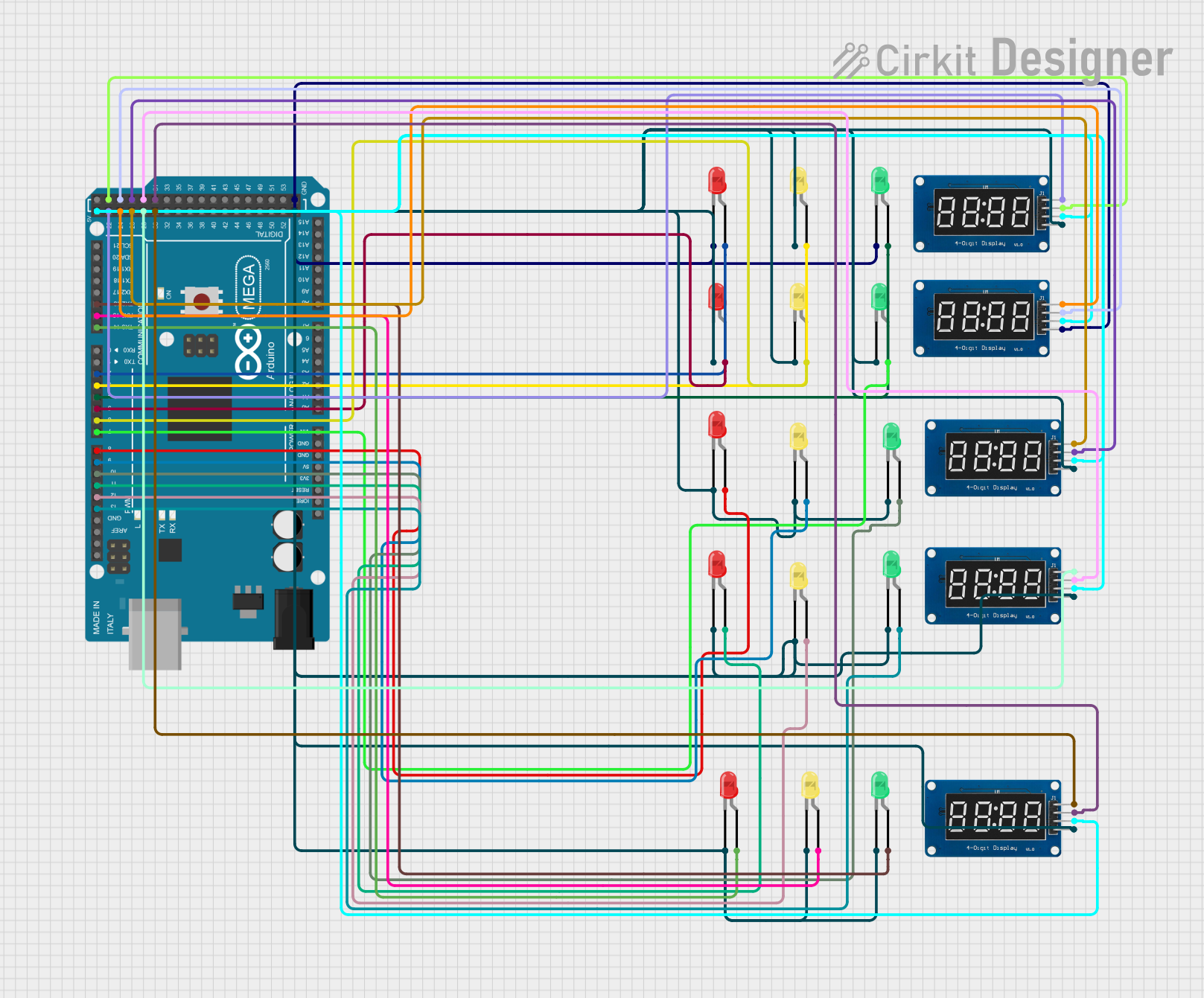
Explore Projects Built with Led Module Yellow
Common Applications
- Status indicators in electronic devices
- Visual feedback in microcontroller projects
- Decorative lighting in DIY projects
- Educational purposes for learning basic electronics
Technical Specifications
The following table outlines the key technical details of the Keyestudio LED Module Yellow:
| Parameter | Specification |
|---|---|
| Operating Voltage | 3.3V to 5V |
| Operating Current | 20mA (typical) |
| LED Color | Yellow |
| Module Dimensions | 18mm x 15mm x 8mm |
| Connector Type | 3-pin header (VCC, GND, Signal) |
| LED Forward Voltage | 2.0V to 2.2V |
| LED Luminous Intensity | 200-300 mcd |
Pin Configuration
The module has a 3-pin header for easy connection. The pin configuration is as follows:
| Pin | Label | Description |
|---|---|---|
| 1 | VCC | Power supply input (3.3V to 5V) |
| 2 | GND | Ground connection |
| 3 | Signal | Control signal to turn the LED on/off |
Usage Instructions
How to Use the LED Module in a Circuit
- Power the Module: Connect the VCC pin to a 3.3V or 5V power source and the GND pin to the ground of your circuit.
- Control the LED: Use the Signal pin to control the LED. You can connect it directly to a microcontroller's digital output pin or use a switch to manually turn the LED on and off.
- Current Limiting Resistor: Although the module includes a built-in resistor, ensure that the current does not exceed 20mA to avoid damaging the LED.
Example: Connecting to an Arduino UNO
Below is an example of how to connect and control the Keyestudio LED Module Yellow using an Arduino UNO:
Circuit Connections
- Connect the VCC pin of the module to the 5V pin on the Arduino.
- Connect the GND pin of the module to the GND pin on the Arduino.
- Connect the Signal pin of the module to digital pin 9 on the Arduino.
Arduino Code
// Keyestudio LED Module Yellow Example
// This code blinks the yellow LED module on and off every second.

const int ledPin = 9; // Pin connected to the Signal pin of the LED module

void setup() {
  pinMode(ledPin, OUTPUT); // Set the LED pin as an output
}

void loop() {
  digitalWrite(ledPin, HIGH); // Turn the LED on
  delay(1000);                // Wait for 1 second
  digitalWrite(ledPin, LOW);  // Turn the LED off
  delay(1000);                // Wait for 1 second
}
Important Considerations
- Voltage Range: Ensure the input voltage is within the specified range (3.3V to 5V).
- Polarity: Double-check the connections to avoid reversing the polarity, which could damage the module.
- Heat Management: Prolonged use at maximum current may generate heat. Allow adequate ventilation.
Troubleshooting and FAQs
Common Issues and Solutions
LED Does Not Light Up
- Cause: Incorrect wiring or insufficient power supply.
- Solution: Verify the connections and ensure the power supply voltage is within the specified range.
LED Flickers or Is Dim
- Cause: Unstable power supply or loose connections.
- Solution: Check the power source and ensure all connections are secure.
LED Stays On Constantly
- Cause: Signal pin is not properly controlled.
- Solution: Verify the control signal from the microcontroller or switch.
Module Overheats
- Cause: Excessive current or prolonged use at maximum current.
- Solution: Reduce the current or add a heat sink if necessary.
FAQs
Q: Can I use this module with a 3.3V microcontroller like ESP32?
A: Yes, the module is compatible with 3.3V systems. Ensure the Signal pin is properly connected to the microcontroller's GPIO pin.
Q: Does the module require an external resistor?
A: No, the module includes a built-in current-limiting resistor, so no additional resistor is needed.
Q: Can I use PWM to control the brightness of the LED?
A: Yes, you can use a PWM signal on the Signal pin to adjust the LED's brightness.
Q: Is the module waterproof?
A: No, the module is not waterproof. Avoid exposing it to moisture or water.
This concludes the documentation for the Keyestudio LED Module Yellow (KS0232). For further assistance, refer to the manufacturer's datasheet or contact technical support.