How to Use ICM20948 : Examples, Pinouts, and Specs
Introduction
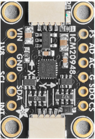
The ICM20948 is a 9-axis motion tracking device that integrates a 3-axis gyroscope, a 3-axis accelerometer, and a 3-axis magnetometer into a single compact chip. This versatile sensor is widely used in applications requiring precise orientation and motion sensing, such as robotics, drones, smartphones, and wearable devices. Its small size, low power consumption, and high accuracy make it an ideal choice for embedded systems and IoT applications.
Explore Projects Built with ICM20948


Explore Projects Built with ICM20948
Technical Specifications
The following table outlines the key technical specifications of the ICM20948:
| Parameter | Value |
|---|---|
| Gyroscope Range | ±250, ±500, ±1000, ±2000 dps |
| Accelerometer Range | ±2g, ±4g, ±8g, ±16g |
| Magnetometer Range | ±4900 µT |
| Gyroscope Sensitivity | 16.4 LSB/dps (at ±2000 dps) |
| Accelerometer Sensitivity | 16384 LSB/g (at ±2g) |
| Magnetometer Sensitivity | 0.15 µT/LSB |
| Operating Voltage | 1.71V to 3.6V |
| Communication Interface | I²C (up to 400 kHz) / SPI (up to 7 MHz) |
| Operating Temperature | -40°C to +85°C |
| Package Size | 3 mm × 3 mm × 1 mm |
Pin Configuration and Descriptions
The ICM20948 is typically available in a 24-pin QFN package. Below is the pin configuration:
| Pin Number | Pin Name | Description |
|---|---|---|
| 1 | VDD | Power supply input (1.71V to 3.6V) |
| 2 | VDDIO | I/O voltage supply |
| 3 | GND | Ground |
| 4 | SCL/SCLK | I²C clock / SPI clock |
| 5 | SDA/SDI | I²C data / SPI data input |
| 6 | SDO/ADO | SPI data output / I²C address select |
| 7 | INT1 | Interrupt 1 output |
| 8 | INT2 | Interrupt 2 output |
| 9-24 | NC | No connection |
Usage Instructions
How to Use the ICM20948 in a Circuit
- Power Supply: Connect the VDD pin to a 1.8V or 3.3V power source and the GND pin to ground.
- Communication Interface: Choose between I²C or SPI for communication:
- For I²C, connect the SCL and SDA pins to the corresponding I²C lines on your microcontroller. Use pull-up resistors (typically 4.7 kΩ) on both lines.
- For SPI, connect SCLK, SDI, and SDO to the SPI lines on your microcontroller. Use the ADO pin to configure the I²C address or as a chip select for SPI.
- Interrupts: If needed, connect INT1 and/or INT2 to your microcontroller for motion event notifications.
- Bypass Mode: To access the magnetometer directly, enable bypass mode via the ICM20948's internal registers.
Important Considerations and Best Practices
- Voltage Levels: Ensure that the I/O voltage (VDDIO) matches the logic level of your microcontroller.
- PCB Layout: Place decoupling capacitors (e.g., 0.1 µF) close to the VDD and VDDIO pins to reduce noise.
- Magnetometer Calibration: Perform a calibration routine to account for hard and soft iron distortions in the environment.
- Sensor Fusion: Use sensor fusion algorithms (e.g., Madgwick or Mahony) to combine data from the gyroscope, accelerometer, and magnetometer for accurate orientation tracking.
Example Code for Arduino UNO
Below is an example of how to interface the ICM20948 with an Arduino UNO using the I²C protocol:
#include <Wire.h>

// ICM20948 I2C address (default is 0x68 when ADO is low)
#define ICM20948_ADDR 0x68

// Register addresses
#define WHO_AM_I 0x00
#define PWR_MGMT_1 0x06
#define ACCEL_XOUT_H 0x2D

void setup() {
  Wire.begin(); // Initialize I2C communication
  Serial.begin(9600); // Initialize serial communication

  // Wake up the ICM20948
  Wire.beginTransmission(ICM20948_ADDR);
  Wire.write(PWR_MGMT_1); // Power management register
  Wire.write(0x01); // Set clock source
  Wire.endTransmission();

  // Verify communication by reading the WHO_AM_I register
  Wire.beginTransmission(ICM20948_ADDR);
  Wire.write(WHO_AM_I);
  Wire.endTransmission();
  Wire.requestFrom(ICM20948_ADDR, 1);

  if (Wire.available()) {
    byte whoAmI = Wire.read();
    Serial.print("WHO_AM_I: 0x");
    Serial.println(whoAmI, HEX);
  } else {
    Serial.println("Failed to communicate with ICM20948");
  }
}

void loop() {
  // Read accelerometer data
  Wire.beginTransmission(ICM20948_ADDR);
  Wire.write(ACCEL_XOUT_H); // Start with the high byte of X-axis
  Wire.endTransmission();
  Wire.requestFrom(ICM20948_ADDR, 6); // Request 6 bytes (X, Y, Z)

  if (Wire.available() == 6) {
    int16_t accelX = (Wire.read() << 8) | Wire.read();
    int16_t accelY = (Wire.read() << 8) | Wire.read();
    int16_t accelZ = (Wire.read() << 8) | Wire.read();

    Serial.print("Accel X: ");
    Serial.print(accelX);
    Serial.print(" Y: ");
    Serial.print(accelY);
    Serial.print(" Z: ");
    Serial.println(accelZ);
  }

  delay(500); // Delay for readability
}
Troubleshooting and FAQs
Common Issues
No Response from the Sensor:
- Ensure the I²C address (default 0x68) matches your configuration.
- Check the wiring, especially the pull-up resistors on the I²C lines.
- Verify that the sensor is powered correctly (VDD and GND connections).
Incorrect or No Data:
- Confirm that the sensor is initialized properly (e.g., PWR_MGMT_1 register).
- Check for noise or interference on the I²C or SPI lines.
- Perform a calibration routine for the accelerometer, gyroscope, and magnetometer.
Magnetometer Not Working:
- Ensure bypass mode is enabled if accessing the magnetometer directly.
- Verify that the magnetometer's registers are being read correctly.
FAQs
Q: Can I use the ICM20948 with a 5V microcontroller?
A: Yes, but you must use a level shifter to convert the 5V logic to 3.3V for the ICM20948.Q: How do I calibrate the sensor?
A: Calibration involves collecting raw data while rotating the sensor in all axes and applying algorithms to compute offsets and scale factors.Q: What is the maximum sampling rate?
A: The ICM20948 supports a maximum output data rate of 1 kHz for the gyroscope and accelerometer.
By following this documentation, you can effectively integrate the ICM20948 into your projects and troubleshoot common issues.