Cirkit Designer Logo
Cirkit Designer
Your all-in-one circuit design IDE
Home / 
Component Documentation

How to Use Brushless ESC: Examples, Pinouts, and Specs

Image of Brushless ESC
Cirkit Designer LogoDesign with Brushless ESC in Cirkit Designer

Introduction

A Brushless Electronic Speed Controller (ESC) is a critical component used to regulate the speed, direction, and braking of brushless motors. It achieves this by controlling the power supplied to the motor, ensuring smooth and precise operation. Manufactured by Robu.in, the Brushless ESC (Part ID: SKU: 1345171) is designed for high-performance applications, including drones, RC vehicles, electric bikes, and robotics.

Explore Projects Built with Brushless ESC

Use Cirkit Designer to design, explore, and prototype these projects online. Some projects support real-time simulation. Click "Open Project" to start designing instantly!
Raspberry Pi-Controlled Drone with Brushless Motors and Camera Module
Image of ROV: A project utilizing Brushless ESC in a practical application
This circuit is designed for a multi-motor application, likely a drone or a similar vehicle, featuring eight brushless motors controlled by two 4-in-1 electronic speed controllers (ESCs). The ESCs are powered by a 3s2p 18650 battery pack and interfaced with a Pixhawk flight controller for motor management. Additionally, the system includes a Raspberry Pi 4B for advanced processing and control, which is connected to a NoIR camera module and a cooling fan, and a power module to supply and monitor the power to the Pixhawk.
Cirkit Designer LogoOpen Project in Cirkit Designer
Quadcopter BLDC Motor Control System with Radio Receiver
Image of rc car: A project utilizing Brushless ESC in a practical application
This circuit is designed to control four Brushless DC (BLDC) motors using corresponding Electronic Speed Controllers (ESCs). Each ESC receives power from a shared LiPo battery and control signals from an FS-CT6B receiver, which likely receives input from a remote transmitter for wireless control. The ESCs regulate the power supplied to the motors based on the received signals, enabling precise speed and direction control of the motors, typically used in applications such as drones or remote-controlled vehicles.
Cirkit Designer LogoOpen Project in Cirkit Designer
Wi-Fi Controlled Brushless Motor System with ESP32 and ESC
Image of BRUSHLESS DC MOTOR: A project utilizing Brushless ESC in a practical application
This circuit controls a brushless motor using an ESP32 microcontroller and an Electronic Speed Controller (ESC). The ESP32 sends control signals to the ESC, which regulates the power from a 12V power supply to drive the motor.
Cirkit Designer LogoOpen Project in Cirkit Designer
ESP32-Controlled Quadcopter with GPS, MPU-6050, and ESP32-CAM
Image of drone: A project utilizing Brushless ESC in a practical application
This circuit is designed for a quadcopter drone with four brushless motors, each controlled by an individual Electronic Speed Controller (ESC). The ESCs receive power from a LiPo battery through a Power Distribution Board (PDB) and are interfaced with an ESP32 microcontroller for signal control. Additional components include an MPU-6050 for motion tracking, a GPS module for positioning, an HC-SR04 ultrasonic sensor for distance measurement, and an ESP32-CAM for image capture, all interfaced with the ESP32 microcontroller which manages sensor data processing and wireless communication.
Cirkit Designer LogoOpen Project in Cirkit Designer

Explore Projects Built with Brushless ESC

Use Cirkit Designer to design, explore, and prototype these projects online. Some projects support real-time simulation. Click "Open Project" to start designing instantly!
Image of ROV: A project utilizing Brushless ESC in a practical application
Raspberry Pi-Controlled Drone with Brushless Motors and Camera Module
This circuit is designed for a multi-motor application, likely a drone or a similar vehicle, featuring eight brushless motors controlled by two 4-in-1 electronic speed controllers (ESCs). The ESCs are powered by a 3s2p 18650 battery pack and interfaced with a Pixhawk flight controller for motor management. Additionally, the system includes a Raspberry Pi 4B for advanced processing and control, which is connected to a NoIR camera module and a cooling fan, and a power module to supply and monitor the power to the Pixhawk.
Cirkit Designer LogoOpen Project in Cirkit Designer
Image of rc car: A project utilizing Brushless ESC in a practical application
Quadcopter BLDC Motor Control System with Radio Receiver
This circuit is designed to control four Brushless DC (BLDC) motors using corresponding Electronic Speed Controllers (ESCs). Each ESC receives power from a shared LiPo battery and control signals from an FS-CT6B receiver, which likely receives input from a remote transmitter for wireless control. The ESCs regulate the power supplied to the motors based on the received signals, enabling precise speed and direction control of the motors, typically used in applications such as drones or remote-controlled vehicles.
Cirkit Designer LogoOpen Project in Cirkit Designer
Image of BRUSHLESS DC MOTOR: A project utilizing Brushless ESC in a practical application
Wi-Fi Controlled Brushless Motor System with ESP32 and ESC
This circuit controls a brushless motor using an ESP32 microcontroller and an Electronic Speed Controller (ESC). The ESP32 sends control signals to the ESC, which regulates the power from a 12V power supply to drive the motor.
Cirkit Designer LogoOpen Project in Cirkit Designer
Image of drone: A project utilizing Brushless ESC in a practical application
ESP32-Controlled Quadcopter with GPS, MPU-6050, and ESP32-CAM
This circuit is designed for a quadcopter drone with four brushless motors, each controlled by an individual Electronic Speed Controller (ESC). The ESCs receive power from a LiPo battery through a Power Distribution Board (PDB) and are interfaced with an ESP32 microcontroller for signal control. Additional components include an MPU-6050 for motion tracking, a GPS module for positioning, an HC-SR04 ultrasonic sensor for distance measurement, and an ESP32-CAM for image capture, all interfaced with the ESP32 microcontroller which manages sensor data processing and wireless communication.
Cirkit Designer LogoOpen Project in Cirkit Designer

Common Applications

  • Drones and Quadcopters: For precise motor control and stable flight.
  • Electric Vehicles: To regulate motor speed and direction.
  • RC Cars and Boats: For smooth acceleration and braking.
  • Robotics: For controlling brushless motors in robotic arms or mobile robots.

Technical Specifications

The following table outlines the key technical details of the Robu.in Brushless ESC:

Specification Value
Manufacturer Robu.in
Part ID SKU: 1345171
Input Voltage Range 7.4V - 22.2V (2S to 6S LiPo batteries)
Continuous Current 30A
Peak Current 40A (for 10 seconds)
Motor Compatibility Brushless DC motors
BEC Output 5V/2A (Battery Eliminator Circuit)
Signal Input PWM (Pulse Width Modulation)
Weight 25g
Dimensions 45mm x 25mm x 8mm
Operating Temperature -10°C to 60°C

Pin Configuration and Descriptions

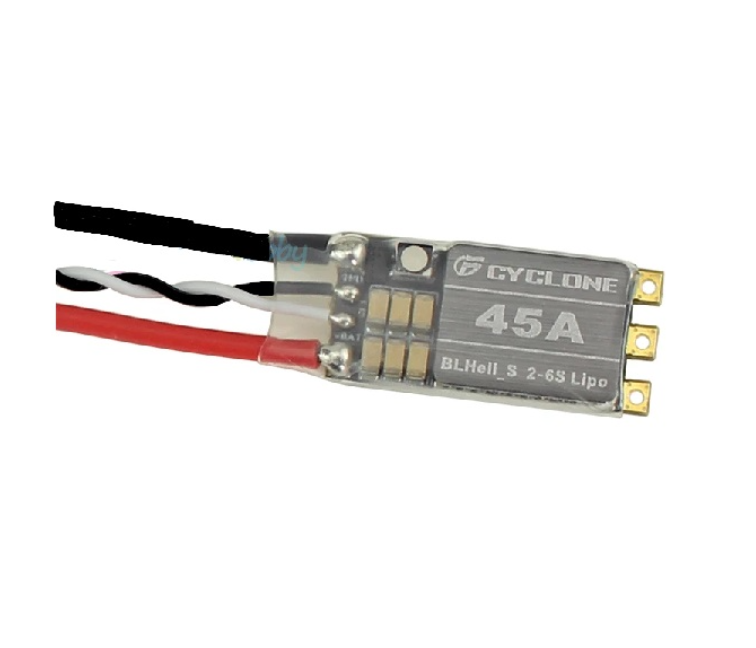
The Brushless ESC has the following pin and wire configuration:

Wire/Pin Description
Red (Thick Wire) Positive input from the battery (VCC).
Black (Thick Wire) Negative input from the battery (GND).
3 Motor Wires Connect to the three terminals of the brushless motor.
Signal Wire (White) PWM signal input from the microcontroller or receiver.
Red (Thin Wire) 5V output from the BEC to power external devices (e.g., microcontroller).
Black (Thin Wire) Ground connection for the BEC output.

Usage Instructions

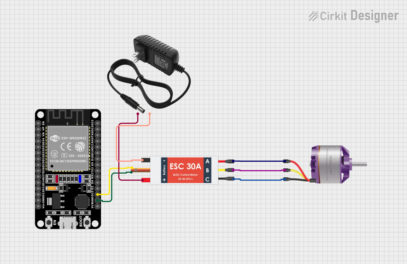
How to Use the Brushless ESC in a Circuit

  1. Connect the Battery: Attach the thick red and black wires to the positive and negative terminals of the battery, respectively.
  2. Connect the Motor: Connect the three motor wires to the brushless motor. If the motor spins in the wrong direction, swap any two wires.
  3. Connect the Signal Wire: Attach the white signal wire to the PWM output pin of your microcontroller or receiver.
  4. Power the Microcontroller: Use the thin red and black wires to power your microcontroller or receiver with the 5V BEC output.
  5. Calibrate the ESC: Follow the ESC calibration procedure (usually involving setting the throttle range) as per the manufacturer’s instructions.
  6. Test the Setup: Gradually increase the throttle signal to test motor operation.

Important Considerations

  • Battery Compatibility: Ensure the battery voltage is within the ESC's input range (7.4V to 22.2V).
  • Cooling: Avoid overheating by ensuring proper airflow or adding a heatsink if necessary.
  • PWM Signal: Use a PWM signal with a frequency of 50Hz to 500Hz for optimal performance.
  • Safety: Always disconnect the battery when making wiring changes to prevent short circuits.

Example Code for Arduino UNO

Below is an example of how to control the Brushless ESC using an Arduino UNO:

#include <Servo.h> // Include the Servo library to generate PWM signals

Servo esc; // Create a Servo object to control the ESC

void setup() {
  esc.attach(9); // Attach the ESC signal wire to pin 9
  esc.writeMicroseconds(1000); // Send minimum throttle signal (1000 µs)
  delay(2000); // Wait for 2 seconds to initialize the ESC
}

void loop() {
  esc.writeMicroseconds(1500); // Set throttle to 50% (1500 µs)
  delay(5000); // Run the motor at 50% throttle for 5 seconds

  esc.writeMicroseconds(1000); // Set throttle to 0% (1000 µs)
  delay(5000); // Stop the motor for 5 seconds
}

Note: Ensure the ESC is calibrated before running the code. Calibration typically involves setting the throttle range by following the ESC's user manual.

Troubleshooting and FAQs

Common Issues and Solutions

  1. Motor Does Not Spin:

    • Cause: Incorrect wiring or no PWM signal.
    • Solution: Verify all connections and ensure the PWM signal is being sent from the microcontroller.
  2. Motor Spins in the Wrong Direction:

    • Cause: Incorrect motor wire connections.
    • Solution: Swap any two of the three motor wires.
  3. ESC Overheats:

    • Cause: Excessive current draw or poor ventilation.
    • Solution: Ensure the motor is not overloaded and improve airflow around the ESC.
  4. No Power to Microcontroller:

    • Cause: BEC output not connected or damaged.
    • Solution: Check the thin red and black wires for proper connection and functionality.

FAQs

  • Q: Can I use this ESC with a brushed motor?
    A: No, this ESC is designed specifically for brushless motors.

  • Q: What happens if I exceed the input voltage range?
    A: Exceeding the voltage range may damage the ESC permanently. Always use a compatible battery.

  • Q: How do I calibrate the ESC?
    A: Calibration typically involves setting the throttle to maximum, powering on the ESC, and then setting the throttle to minimum. Refer to the ESC's user manual for detailed steps.

  • Q: Can I use this ESC without a microcontroller?
    A: Yes, you can use it with an RC receiver that outputs a PWM signal.

This concludes the documentation for the Robu.in Brushless ESC (SKU: 1345171). For further assistance, refer to the manufacturer's support resources.