How to Use 12v FUSEBOARD: Examples, Pinouts, and Specs
12V Fuseboard Documentation
1. Introduction
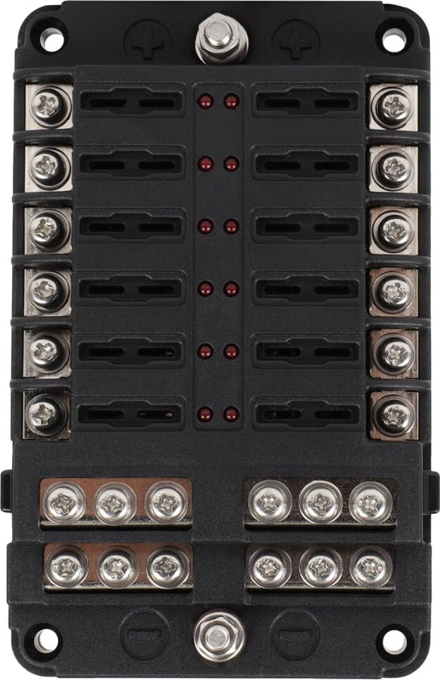
The 12V Fuseboard is a compact and efficient panel designed to house multiple fuses for protecting electrical circuits operating at 12 volts. It serves as a centralized hub for distributing power to various components in a system while ensuring safety by interrupting the circuit in the event of an overload or short circuit. This component is essential in automotive, marine, and other low-voltage DC applications where multiple circuits need to be protected.
Common Applications:
- Automotive Systems: Protecting circuits for lights, radios, and other accessories.
- Marine Applications: Safeguarding electrical systems in boats and yachts.
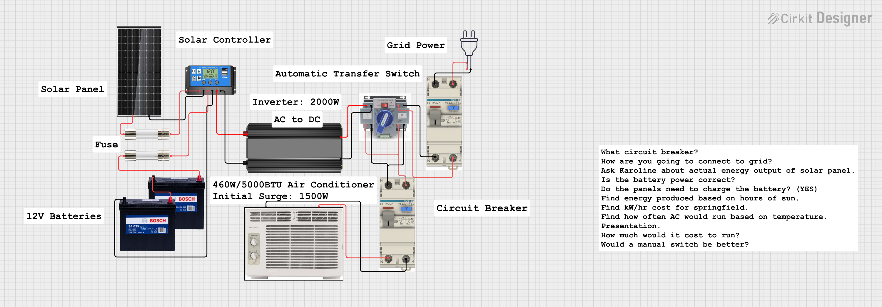
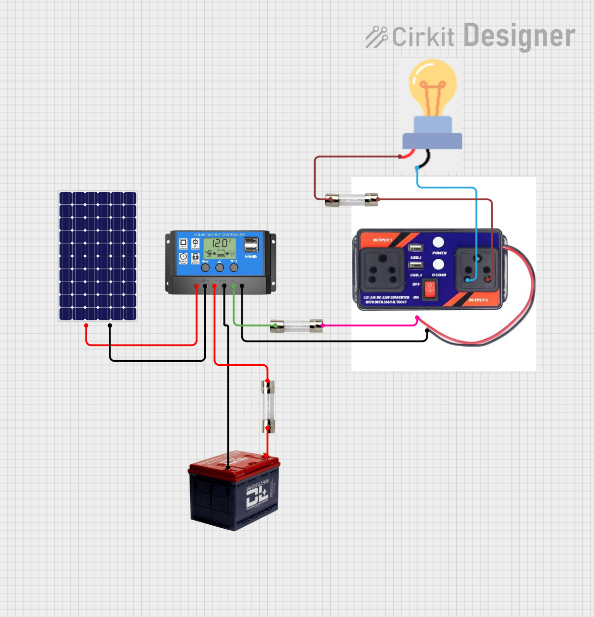
- Solar Power Systems: Distributing and protecting power from 12V solar panels.
- DIY Electronics Projects: Managing multiple low-voltage circuits safely.
- Home Automation: Powering and protecting 12V devices like relays, sensors, and actuators.
2. Technical Specifications
The following table outlines the key technical details of the 12V Fuseboard:
| Parameter | Specification |
|---|---|
| Operating Voltage | 12V DC |
| Maximum Current Rating | 30A per circuit (varies based on fuse rating) |
| Number of Fuse Slots | 6, 8, or 12 (depending on the model) |
| Fuse Type | Standard blade fuses (ATO/ATC type) |
| Input Connection | Screw terminal or spade connector |
| Output Connections | Screw terminals or spade connectors for each circuit |
| Indicator LEDs | Optional (lights up when a fuse is blown) |
| Mounting Style | Panel mount or surface mount |
| Material | Flame-retardant plastic housing |
| Dimensions | Varies by model (e.g., 100mm x 50mm x 30mm) |
Pin Configuration and Descriptions
| Pin/Terminal | Description |
|---|---|
| Input (+) | Positive 12V DC input terminal. Connect to the positive terminal of the power source. |
| Input (-) | Ground terminal. Connect to the negative terminal of the power source. |
| Output 1-12 | Positive output terminals for each circuit. Connect to the load (e.g., lights, motors). |
| Fuse Slots | Slots for blade fuses. Each slot corresponds to an output circuit. |
3. Usage Instructions
How to Use the 12V Fuseboard in a Circuit:
Power Source Connection:
- Connect the positive terminal of your 12V DC power source to the Input (+) terminal of the fuseboard.
- Connect the negative terminal of your power source to the Input (-) terminal.
Fuse Installation:
- Insert the appropriate blade fuses into the fuse slots. The fuse rating should match the current requirements of the connected load.
Load Connection:
- Connect the positive wire of each load (e.g., light, motor, or sensor) to the corresponding output terminal on the fuseboard.
- Connect the negative wire of each load to the ground (common negative).
Testing:
- Power on the system and verify that all connected devices are functioning correctly.
- If a circuit is overloaded or shorted, the corresponding fuse will blow, protecting the circuit.
Important Considerations:
- Always use fuses with the correct current rating to avoid damage to the fuseboard or connected devices.
- Ensure all connections are secure to prevent loose wires, which can cause overheating or arcing.
- If the fuseboard includes indicator LEDs, check for any illuminated LEDs, which indicate a blown fuse.
- Avoid exceeding the maximum current rating of the fuseboard.
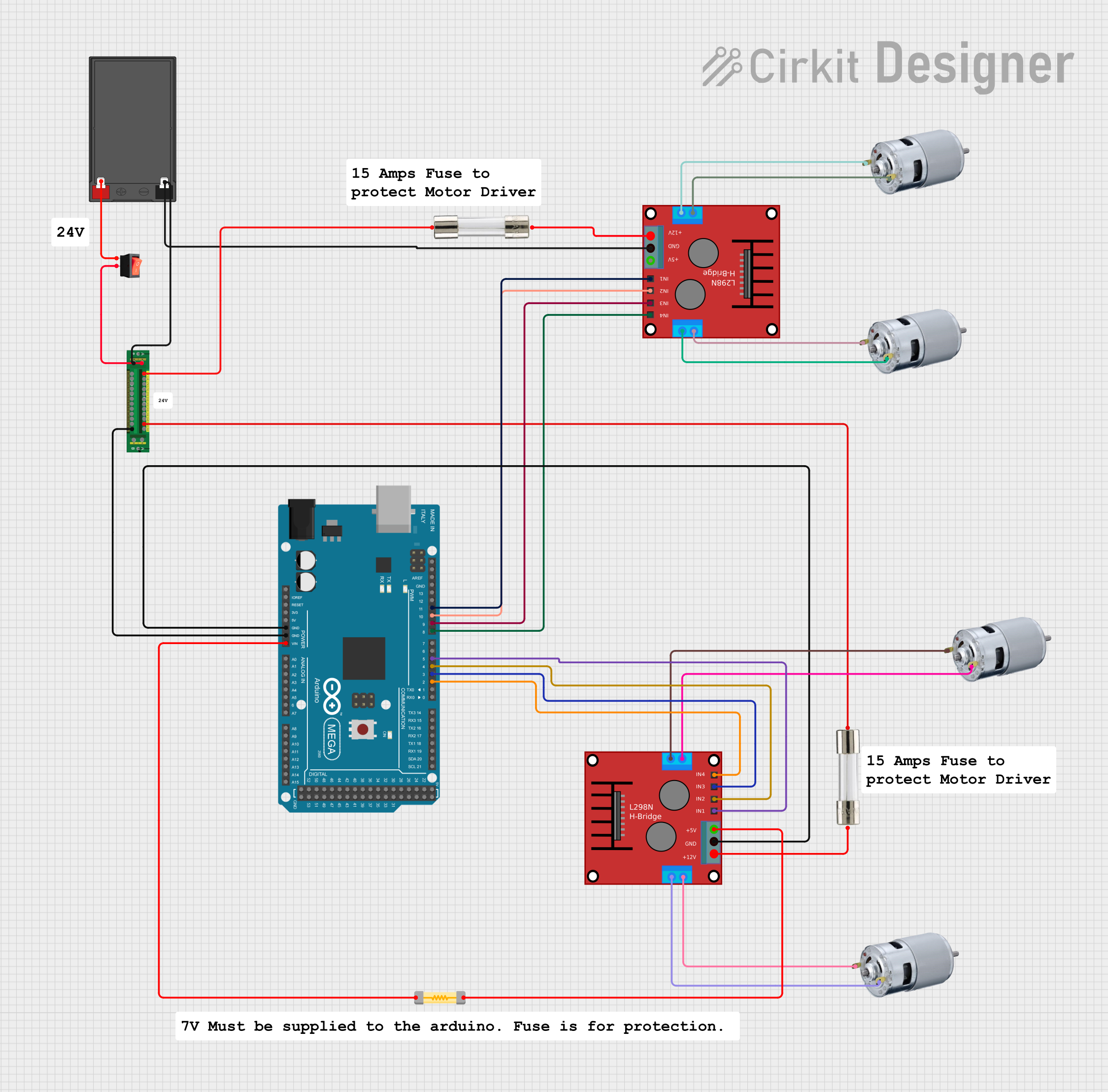
4. Example Application with Arduino UNO
The 12V Fuseboard can be used in projects involving an Arduino UNO to protect connected components. Below is an example of how to use the fuseboard to power a 12V DC motor controlled by an Arduino.
Circuit Diagram:
- Power Source: 12V DC
- Fuseboard: Protects the motor circuit
- Arduino UNO: Controls the motor via a relay module
Code Example:
// Example code to control a 12V DC motor using Arduino and a relay module
// Ensure the motor is connected to the fuseboard for circuit protection

const int relayPin = 7; // Pin connected to the relay module

void setup() {
  pinMode(relayPin, OUTPUT); // Set relay pin as output
  digitalWrite(relayPin, LOW); // Ensure relay is off at startup
}

void loop() {
  // Turn the motor ON
  digitalWrite(relayPin, HIGH); // Activate relay
  delay(5000); // Keep motor running for 5 seconds

  // Turn the motor OFF
  digitalWrite(relayPin, LOW); // Deactivate relay
  delay(5000); // Wait for 5 seconds before restarting
}
Notes:
- Connect the relay module's input pin to the Arduino's digital pin 7.
- The motor's positive terminal should be connected to the fuseboard's output terminal, and the negative terminal should be connected to ground.
- Use a fuse rated for the motor's current draw.
5. Troubleshooting and FAQs
Common Issues and Solutions:
| Issue | Possible Cause | Solution |
|---|---|---|
| No power to connected devices | Blown fuse | Replace the blown fuse with one of the correct rating. |
| Fuse blows repeatedly | Overloaded circuit or short circuit | Check the load for excessive current draw or wiring faults. |
| Indicator LED not lighting up | LED malfunction or no blown fuse | Verify the LED functionality or check the fuse status. |
| Loose connections | Improperly secured wires | Tighten all connections and ensure proper contact. |
FAQs:
Can I use the 12V Fuseboard with a 24V system?
- No, the fuseboard is designed for 12V DC systems. Using it with higher voltages may damage the board or connected devices.
What type of fuses should I use?
- Use standard blade fuses (ATO/ATC type) with a current rating suitable for your circuit.
How do I know if a fuse is blown?
- If the fuseboard has indicator LEDs, a blown fuse will cause the corresponding LED to light up. Otherwise, visually inspect the fuse for a broken filament.
Can I connect multiple devices to a single output?
- Yes, but ensure the total current draw does not exceed the fuse rating for that circuit.
This documentation provides a comprehensive guide to understanding, using, and troubleshooting the 12V Fuseboard. Whether you're a beginner or an experienced user, this guide will help you integrate the fuseboard into your projects safely and effectively.
Explore Projects Built with 12v FUSEBOARD
Explore Projects Built with 12v FUSEBOARD