How to Use DC-DC Boost -generic: Examples, Pinouts, and Specs
Introduction
A DC-DC boost converter is a power electronic device designed to step up (increase) the input voltage to a higher output voltage while maintaining the same polarity. It achieves this by using inductors, capacitors, diodes, and switching elements to efficiently transfer energy. This component is widely used in applications where a higher voltage is required from a lower voltage source, such as in battery-powered devices, renewable energy systems, and automotive electronics.
Explore Projects Built with DC-DC Boost -generic


Explore Projects Built with DC-DC Boost -generic
Common Applications:
- Powering high-voltage devices from low-voltage batteries
- Solar power systems to increase panel output voltage
- LED drivers for high-power LEDs
- Electric vehicles and hybrid systems
- Portable electronics requiring voltage regulation
Technical Specifications
Below are the general technical specifications for a generic DC-DC boost converter. Specific values may vary depending on the model.
Key Specifications:
- Input Voltage Range: 3V to 32V
- Output Voltage Range: 5V to 35V (adjustable via potentiometer)
- Maximum Output Current: 2A (continuous), 3A (peak)
- Efficiency: Up to 95% (depending on input/output voltage and load)
- Switching Frequency: 150 kHz
- Operating Temperature: -40°C to +85°C
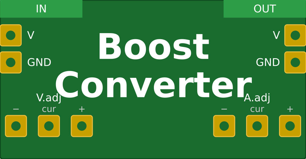
Pin Configuration and Descriptions:
| Pin Name | Description |
|---|---|
| VIN | Positive input voltage terminal |
| GND | Ground terminal (common ground) |
| VOUT | Positive output voltage terminal |
| ADJ | Voltage adjustment (via potentiometer or external resistor) |
Usage Instructions
How to Use the DC-DC Boost Converter in a Circuit:
- Connect the Input Voltage:
- Connect the positive terminal of your power source to the
VINpin. - Connect the negative terminal of your power source to the
GNDpin.
- Connect the positive terminal of your power source to the
- Connect the Output Load:
- Connect the positive terminal of your load to the
VOUTpin. - Connect the negative terminal of your load to the
GNDpin.
- Connect the positive terminal of your load to the
- Adjust the Output Voltage:
- Use the onboard potentiometer to set the desired output voltage.
- Measure the output voltage with a multimeter while adjusting to ensure accuracy.
- Power On:
- Turn on the power source and verify the output voltage and current.
Important Considerations:
- Input Voltage: Ensure the input voltage is within the specified range (3V to 32V). Exceeding this range may damage the converter.
- Output Voltage: Do not set the output voltage higher than the rated maximum (35V).
- Load Current: Ensure the load does not exceed the maximum rated current (2A continuous, 3A peak).
- Heat Dissipation: For high-power applications, consider adding a heatsink to the converter to prevent overheating.
- Polarity: Always connect the input and output terminals with the correct polarity to avoid damage.
Example: Using with an Arduino UNO
The DC-DC boost converter can be used to power an Arduino UNO from a low-voltage source, such as a 3.7V Li-ion battery. Below is an example circuit and code to read the boosted voltage using the Arduino's analog input.
Circuit:
- Connect the battery's positive terminal to the
VINpin of the boost converter. - Connect the battery's negative terminal to the
GNDpin of the boost converter. - Connect the
VOUTpin of the boost converter to the Arduino'sVINpin. - Connect the
GNDpin of the boost converter to the Arduino'sGND.
Code:
// Arduino code to read the boosted voltage using an analog pin
const int voltagePin = A0; // Analog pin connected to the output voltage
float referenceVoltage = 5.0; // Arduino reference voltage (5V for UNO)
float voltageDividerRatio = 5.7; // Adjust based on resistor divider used

void setup() {
  Serial.begin(9600); // Initialize serial communication
  pinMode(voltagePin, INPUT); // Set the voltage pin as input
}

void loop() {
  int analogValue = analogRead(voltagePin); // Read the analog value
  // Calculate the actual voltage using the ADC value and divider ratio
  float outputVoltage = (analogValue * referenceVoltage / 1023.0) * voltageDividerRatio;

  // Print the voltage to the Serial Monitor
  Serial.print("Boosted Voltage: ");
  Serial.print(outputVoltage);
  Serial.println(" V");

  delay(1000); // Wait for 1 second before the next reading
}
Note: Use a voltage divider circuit if the output voltage exceeds the Arduino's ADC input range (0-5V).
Troubleshooting and FAQs
Common Issues:
- No Output Voltage:
- Check the input voltage and ensure it is within the specified range.
- Verify all connections and ensure correct polarity.
- Inspect the potentiometer setting; it may need adjustment.
- Overheating:
- Ensure the load current does not exceed the rated maximum.
- Add a heatsink or improve ventilation if necessary.
- Output Voltage Fluctuations:
- Check for loose connections or poor solder joints.
- Ensure the input voltage is stable and not dropping under load.
- Low Efficiency:
- Verify that the input and output voltage difference is not excessive.
- Use shorter wires to reduce resistance and power loss.
FAQs:
Q1: Can I use this converter to power a 12V device from a 5V USB source?
A1: Yes, as long as the input current from the USB source does not exceed its limit and the load current is within the converter's rated capacity.
Q2: How do I calculate the input current required for my load?
A2: Use the formula:
[
I_{in} = \frac{V_{out} \times I_{out}}{V_{in} \times \text{Efficiency}}
]
For example, if your load requires 12V at 1A, and the input is 5V with 90% efficiency:
[
I_{in} = \frac{12 \times 1}{5 \times 0.9} = 2.67A
]
Q3: Can I use this converter with a solar panel?
A3: Yes, but ensure the panel's output voltage and current are within the converter's input range. Use capacitors to stabilize the input voltage if needed.
By following this documentation, you can effectively integrate a DC-DC boost converter into your projects and troubleshoot common issues.