How to Use 4x4 Keypad (Simulator): Examples, Pinouts, and Specs
Introduction
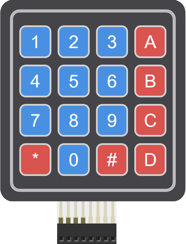
The 4x4 Keypad is a simulated electronic component that emulates the functionality of a physical 4x4 matrix keypad. It is commonly used as an input device in various electronic projects, including security systems, telephone dial pads, and calculators. The keypad consists of 16 buttons arranged in a 4x4 grid, allowing for input of numbers, letters, and other characters.
Explore Projects Built with 4x4 Keypad (Simulator)
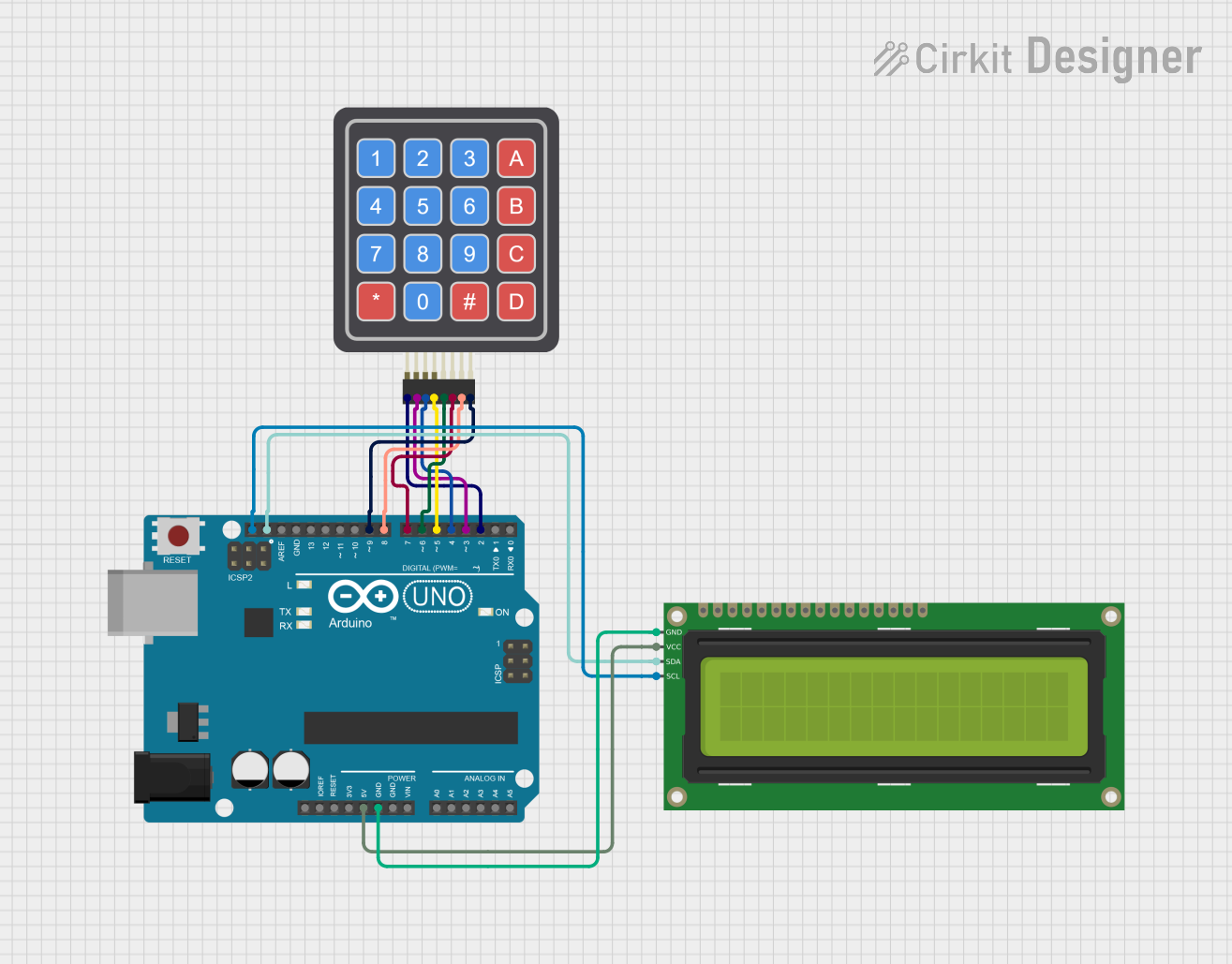

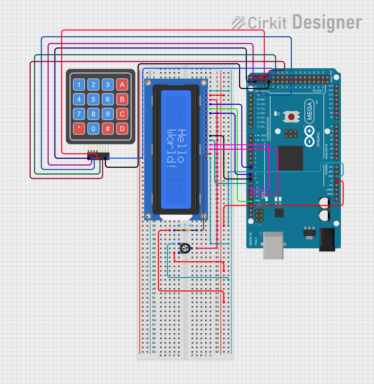
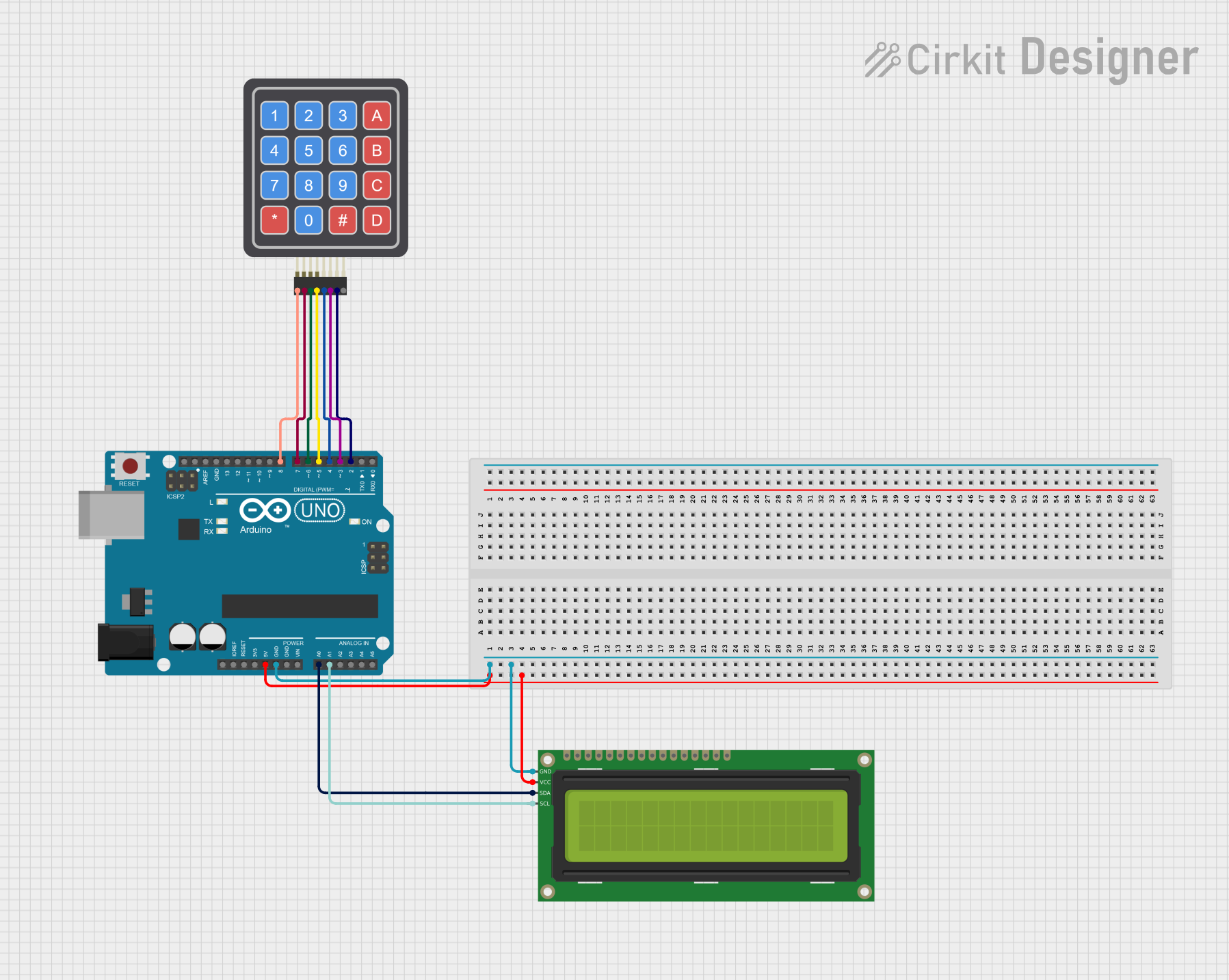
Explore Projects Built with 4x4 Keypad (Simulator)
Technical Specifications
Key Technical Details
- Operating Voltage: Typically 3.3V to 5V
- Interface: 8-pin matrix
- Contact Type: Momentary tactile switches
- Life Expectancy: Varies by simulation parameters (not applicable for physical wear)
Pin Configuration and Descriptions
| Pin Number | Description |
|---|---|
| 1 | Row 1 |
| 2 | Row 2 |
| 3 | Row 3 |
| 4 | Row 4 |
| 5 | Column 1 |
| 6 | Column 2 |
| 7 | Column 3 |
| 8 | Column 4 |
Usage Instructions
How to Use the Component in a Circuit
- Connect Rows to Microcontroller Pins: Connect each row pin (1-4) to a separate digital pin on your microcontroller.
- Connect Columns to Microcontroller Pins: Connect each column pin (5-8) to a separate digital pin on your microcontroller.
- Programming: Write or upload a program to your microcontroller to scan the keypad and detect button presses.
- Debouncing: Implement software debouncing to ensure accurate button press detection.
Important Considerations and Best Practices
- Voltage Levels: Ensure that the operating voltage of the keypad matches that of the microcontroller to prevent damage.
- Pull-up Resistors: Use either internal or external pull-up resistors on the row pins to ensure a defined logic level when buttons are not pressed.
- Scanning Interval: Adjust the scanning interval to balance between responsiveness and processor load.
Example Code for Arduino UNO
#include <Keypad.h>

const byte ROWS = 4; // Four rows
const byte COLS = 4; // Four columns

// Define the Keymap
char keys[ROWS][COLS] = {
  {'1', '2', '3', 'A'},
  {'4', '5', '6', 'B'},
  {'7', '8', '9', 'C'},
  {'*', '0', '#', 'D'}
};

// Connect keypad ROW0, ROW1, ROW2 and ROW3 to these Arduino pins.
byte rowPins[ROWS] = {9, 8, 7, 6};

// Connect keypad COL0, COL1, COL2 and COL3 to these Arduino pins.
byte colPins[COLS] = {5, 4, 3, 2};

// Create the Keypad
Keypad keypad = Keypad(makeKeymap(keys), rowPins, colPins, ROWS, COLS);

void setup() {
  Serial.begin(9600);
}

void loop() {
  char key = keypad.getKey();

  if (key) {
    Serial.println(key);
  }
}
Troubleshooting and FAQs
Common Issues
- No response when pressing keys: Check connections and ensure the keypad is properly wired to the microcontroller.
- Incorrect characters displayed: Verify the keymap in the code matches the physical layout of the keypad.
- Multiple keypresses registered for a single press: Implement or adjust debouncing in the code.
Solutions and Tips for Troubleshooting
- Check Wiring: Ensure all connections are secure and correspond to the correct pins on the microcontroller.
- Serial Output: Use
Serial.printstatements to debug the output of each key press. - Debounce Logic: Adjust the debounce timing in the code to prevent false detections.
FAQs
Q: Can I use the 4x4 Keypad with a 3.3V microcontroller? A: Yes, but ensure that the logic levels are compatible and adjust the voltage if necessary.
Q: How can I detect simultaneous keypresses? A: The standard library may not support multi-key detection. You may need to modify the library or write custom code to handle this.
Q: What is debouncing and why is it important? A: Debouncing is the process of eliminating false or repeated readings due to the mechanical nature of switch contacts. It is important for accurate keypress detection.