How to Use MX1508 Driver: Examples, Pinouts, and Specs

Introduction
The MX1508 Dual DC Motor Driver Module is a compact and efficient motor driver designed for controlling two DC motors or a single stepper motor. It features a dual H-bridge configuration, allowing for bidirectional control of motors. The module is capable of controlling motor speed and direction using Pulse Width Modulation (PWM) signals, making it ideal for robotics, automation, and other motor control applications.
Explore Projects Built with MX1508 Driver

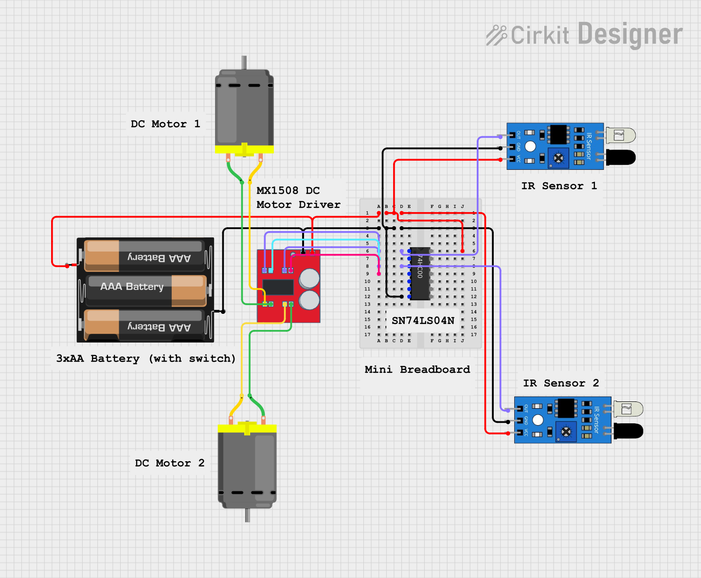

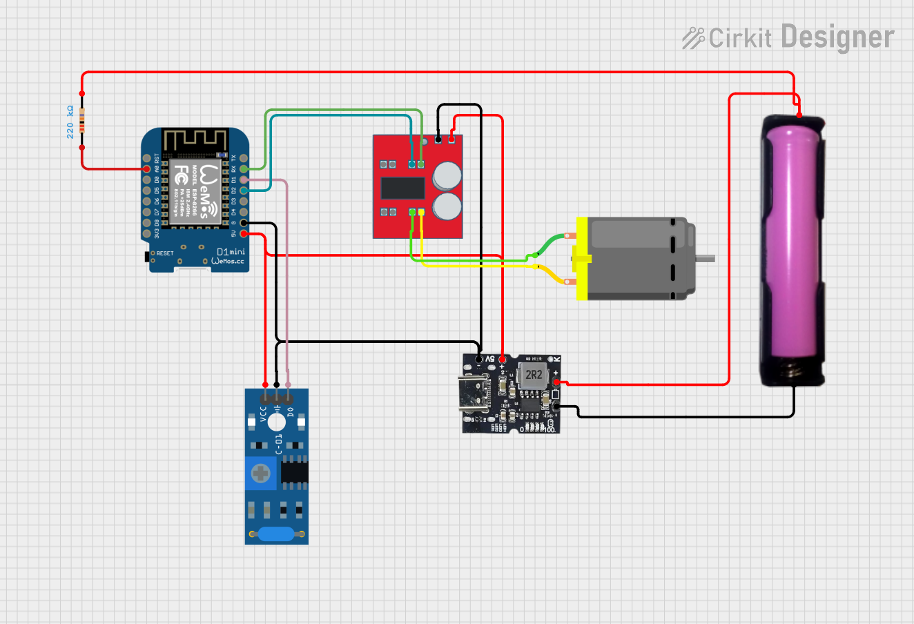
Explore Projects Built with MX1508 Driver
Common Applications
- Robotics and automation systems
- DIY motorized projects
- Remote-controlled vehicles
- Conveyor belts and small machinery
- Educational projects involving motor control
Technical Specifications
The following table outlines the key technical details of the MX1508 module:
| Parameter | Specification |
|---|---|
| Operating Voltage | 2.0V to 10.0V |
| Output Current (per channel) | 1.5A (continuous), 2.5A (peak) |
| Control Signal Voltage | 1.8V to 5.0V (logic level) |
| Motor Channels | 2 (independent control) |
| PWM Frequency | Up to 20 kHz |
| Dimensions | 24mm x 21mm x 5mm |
| Weight | ~3g |
Pin Configuration and Descriptions
The MX1508 module has 8 pins, as described in the table below:
| Pin | Name | Description |
|---|---|---|
| 1 | VCC | Power supply input (2.0V to 10.0V). Connect to the motor power source. |
| 2 | GND | Ground connection. |
| 3 | INA | Input signal for Motor A direction control. |
| 4 | INB | Input signal for Motor A speed control (PWM). |
| 5 | OUTA+ | Positive output terminal for Motor A. |
| 6 | OUTA- | Negative output terminal for Motor A. |
| 7 | OUTB+ | Positive output terminal for Motor B. |
| 8 | OUTB- | Negative output terminal for Motor B. |
Usage Instructions
Connecting the MX1508 to a Circuit
- Power Supply: Connect the
VCCpin to a power source (2.0V to 10.0V) suitable for your motors. Connect theGNDpin to the ground of the power source. - Motor Connections:
- For Motor A, connect its terminals to
OUTA+andOUTA-. - For Motor B, connect its terminals to
OUTB+andOUTB-.
- For Motor A, connect its terminals to
- Control Signals:
- Use the
INAandINBpins to control Motor A's direction and speed. - Similarly, use the corresponding control pins for Motor B.
- Use the
Controlling the Motors with an Arduino UNO
The MX1508 can be easily interfaced with an Arduino UNO. Below is an example code snippet to control two DC motors:
// Define control pins for Motor A
const int INA = 9;  // Direction control for Motor A
const int INB = 10; // Speed control (PWM) for Motor A

// Define control pins for Motor B
const int IN1 = 11; // Direction control for Motor B
const int IN2 = 12; // Speed control (PWM) for Motor B

void setup() {
  // Set motor control pins as outputs
  pinMode(INA, OUTPUT);
  pinMode(INB, OUTPUT);
  pinMode(IN1, OUTPUT);
  pinMode(IN2, OUTPUT);
}

void loop() {
  // Example: Run Motor A forward at 50% speed
  digitalWrite(INA, HIGH);  // Set direction
  analogWrite(INB, 128);    // Set speed (0-255)

  // Example: Run Motor B backward at 75% speed
  digitalWrite(IN1, LOW);   // Set direction
  analogWrite(IN2, 192);    // Set speed (0-255)

  delay(2000); // Run motors for 2 seconds

  // Stop both motors
  analogWrite(INB, 0);
  analogWrite(IN2, 0);

  delay(2000); // Wait for 2 seconds
}
Important Considerations
- Ensure the power supply voltage matches the motor's operating voltage range.
- Avoid exceeding the maximum current rating (1.5A continuous, 2.5A peak) to prevent damage.
- Use appropriate heat dissipation methods if operating near the peak current for extended periods.
- Always connect the ground of the control circuit (e.g., Arduino) to the
GNDpin of the MX1508 module.
Troubleshooting and FAQs
Common Issues
Motors not running:
- Verify that the power supply voltage is within the specified range.
- Check the connections to the motor terminals and control pins.
- Ensure the control signals (PWM and direction) are correctly configured.
Motor running in the wrong direction:
- Swap the connections to the motor terminals (
OUTA+andOUTA-orOUTB+andOUTB-). - Verify the logic level of the direction control pins (
INAorIN1).
- Swap the connections to the motor terminals (
Overheating:
- Ensure the current drawn by the motors does not exceed the module's maximum rating.
- Add a heatsink or improve ventilation if necessary.
PWM signal not working:
- Confirm that the PWM frequency is within the module's supported range (up to 20 kHz).
- Check the Arduino code for errors in the
analogWritefunction.
FAQs
Q1: Can the MX1508 drive stepper motors?
Yes, the MX1508 can drive a single stepper motor by controlling its two coils. However, additional logic or a library may be required for precise stepper motor control.
Q2: What is the maximum motor voltage supported?
The module supports motor voltages up to 10V. Ensure your motor's voltage is within this range.
Q3: Can I use the MX1508 with a 3.3V microcontroller?
Yes, the MX1508 supports control signal voltages as low as 1.8V, making it compatible with 3.3V microcontrollers.
Q4: Is it possible to control motor speed without PWM?
No, PWM is required to achieve variable speed control. Without PWM, the motor will run at full speed when powered.
By following this documentation, you can effectively use the MX1508 Dual DC Motor Driver Module in your projects.