How to Use Buck Boost Converter: Examples, Pinouts, and Specs
Introduction
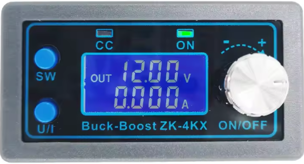
A Buck Boost Converter is a type of DC-DC converter that can step up (boost) or step down (buck) an input voltage to a desired output voltage level. This versatility makes it an essential component in power supply applications where the input voltage may vary but a stable output voltage is required. It is widely used in battery-powered devices, renewable energy systems, and embedded electronics.
Explore Projects Built with Buck Boost Converter


Explore Projects Built with Buck Boost Converter
Common Applications and Use Cases
- Powering microcontrollers and sensors from batteries with varying charge levels
- Voltage regulation in renewable energy systems (e.g., solar panels)
- Portable electronic devices requiring stable voltage
- Automotive electronics for managing varying input voltages
- LED drivers and lighting systems
Technical Specifications
Below are the general technical specifications for a typical Buck Boost Converter. Note that specific models may vary, so always refer to the datasheet of the exact component you are using.
Key Technical Details
- Input Voltage Range: 2V to 36V (varies by model)
- Output Voltage Range: 1.2V to 24V (adjustable or fixed, depending on the model)
- Output Current: Up to 3A (varies by model)
- Efficiency: Up to 95% (depending on load and input/output conditions)
- Switching Frequency: 100kHz to 1MHz
- Operating Temperature: -40°C to +85°C
Pin Configuration and Descriptions
The pinout of a Buck Boost Converter module may vary depending on the specific design. Below is an example of a common pin configuration:
| Pin Name | Description |
|---|---|
| VIN | Input voltage pin. Connect the input power source here. |
| GND | Ground pin. Connect to the ground of the circuit. |
| VOUT | Output voltage pin. Provides the regulated output voltage. |
| EN | Enable pin. Used to turn the converter on or off (active high). |
| FB | Feedback pin. Used to set or monitor the output voltage (via a resistor divider). |
| SW | Switching pin. Connects to the inductor in the circuit. |
Usage Instructions
How to Use the Component in a Circuit
- Connect the Input Voltage: Attach the positive terminal of your power source to the VIN pin and the negative terminal to the GND pin.
- Set the Output Voltage: If the converter has an adjustable output, use a potentiometer or resistor divider connected to the FB pin to set the desired output voltage.
- Connect the Load: Attach the positive terminal of your load to the VOUT pin and the negative terminal to GND.
- Enable the Converter: If the module has an EN pin, ensure it is pulled high to enable the converter. If unused, connect it to VIN.
- Add External Components: Depending on the design, you may need to add an external inductor, capacitors, or diodes as specified in the datasheet.
Important Considerations and Best Practices
- Input Voltage Range: Ensure the input voltage is within the specified range of the converter to avoid damage.
- Heat Dissipation: Buck Boost Converters can generate heat during operation. Use a heatsink or ensure proper ventilation if necessary.
- Inductor Selection: If using a discrete converter IC, choose an inductor with the correct inductance and current rating as specified in the datasheet.
- Output Capacitors: Use low-ESR capacitors to minimize voltage ripple at the output.
- Load Current: Do not exceed the maximum output current rating of the converter.
Example: Using a Buck Boost Converter with Arduino UNO
Below is an example of how to use a Buck Boost Converter to power an Arduino UNO from a 3.7V lithium-ion battery:
- Connect the battery's positive terminal to the VIN pin and the negative terminal to GND.
- Adjust the output voltage of the converter to 5V using the onboard potentiometer.
- Connect the VOUT pin to the Arduino's 5V pin and GND to GND.
Arduino Code Example
If the Buck Boost Converter is used to power sensors or peripherals, you can use the following code to read sensor data:
// Example code to read data from a sensor powered by a Buck Boost Converter
// connected to an Arduino UNO. Ensure the converter output is set to 5V.

const int sensorPin = A0; // Analog pin connected to the sensor output
int sensorValue = 0;      // Variable to store the sensor reading

void setup() {
  Serial.begin(9600); // Initialize serial communication at 9600 baud
  pinMode(sensorPin, INPUT); // Set the sensor pin as input
}

void loop() {
  sensorValue = analogRead(sensorPin); // Read the sensor value
  Serial.print("Sensor Value: ");
  Serial.println(sensorValue); // Print the sensor value to the Serial Monitor
  delay(1000); // Wait for 1 second before the next reading
}
Troubleshooting and FAQs
Common Issues and Solutions
No Output Voltage
- Cause: Input voltage is not connected or is outside the specified range.
- Solution: Verify the input voltage and connections.
Output Voltage is Incorrect
- Cause: Feedback resistor or potentiometer is not set correctly.
- Solution: Adjust the potentiometer or verify the resistor values.
Excessive Heat
- Cause: Overloading the converter or insufficient cooling.
- Solution: Reduce the load current or add a heatsink.
High Output Ripple
- Cause: Insufficient output capacitance or poor capacitor quality.
- Solution: Use low-ESR capacitors and ensure proper placement.
FAQs
Q: Can I use a Buck Boost Converter to power a Raspberry Pi?
A: Yes, but ensure the converter can supply the required current (typically 2.5A for Raspberry Pi 4) and set the output voltage to 5V.
Q: What happens if I reverse the input polarity?
A: Most Buck Boost Converters do not have reverse polarity protection. This can damage the module. Use a diode or a protection circuit to prevent this.
Q: Can I use the converter with an AC input?
A: No, Buck Boost Converters are designed for DC input only. Use a rectifier and filter circuit to convert AC to DC before using the converter.
Q: How do I calculate the required inductor value for a discrete Buck Boost IC?
A: Refer to the IC's datasheet, which typically provides formulas or recommended values based on the input/output voltage and current.
By following this documentation, you can effectively use a Buck Boost Converter in your projects and troubleshoot common issues. Always consult the specific datasheet for your module or IC for precise details.